Stent alignment during treatment of a bifurcation

a bifurcation and stent technology, applied in the field of medical devices, can solve the problems of limited success rate, stents and connecting balloon catheter portions may obstruct the use of post-operative devices to treat a daughter vessel, and stents are not fully able to prevent in-stent restnosis (isr) or caused restnosis

Active Publication Date: 2014-08-19
ADVANCED BIFURCATION SYST
View PDF586 Cites 24 Cited by
  • Summary
  • Abstract
  • Description
  • Claims
  • Application Information

AI Technical Summary

Benefits of technology

[0021]The plurality of axial elements may comprise one or more struts formed into a series of peaks and valleys, and the plurality of lateral elements may comprise one or more struts formed into a series of peaks and valleys. The step of interdigitating may comprise positioning a peak on one of the axial elements into a valley on a lateral element, or positioning a peak on one of the lateral elements into a valley on one of the axial elements. The interdigitating axial and lateral elements may provide uniform or continuous scaffolding around the bifurcation.
[0024]The method may further comprise radially expanding the second expandable member, thereby further expanding the proximal portion of the second stent and expanding a distal portion of the second stent into engagement with a wall of the main branch. The method may also comprise simultaneously expanding the first and the second expandable members into engagement with one another thereby ensuring engagement of the first stent with the side branch lesion and engagement of the second stent with the main branch lesion. This also ensures alignment of a proximal end of the first stent with the side hole in the second stent. Alignment may be achieved without distorting the vessel or without distorting the stent struts beyond their intended deformation configuration.
[0026]The method may further comprise radially expanding the second expandable member, thereby further expanding the proximal portion of the second stent and expanding a distal portion of the second stent into engagement with a wall of the side branch. The method may also comprise simultaneously expanding the first and the second expandable members into engagement with one another. This ensures engagement of the first stent with the main branch lesion and ensures engagement of the second stent with the side branch lesion, as well as ensuring alignment of a proximal end of the first stent with the side hole in the second stent. Alignment may be achieved without distorting the vessel or without distorting the stent struts beyond their intended deformation configuration.

Problems solved by technology

Conventional stents have been used for treating more complex vascular problems, such as lesions at or near bifurcation points in the vascular system, where a secondary artery branches out of a typically larger, main artery, with limited success rates.
Furthermore, the configuration of struts and connecting balloon catheter portions may obstruct the use of post-operative devices to treat a daughter vessel in the region of a vessel bifurcation.
Regular stent design has typically compromised one consideration for the other in an attempt to address both.
Although conventional stents are routinely used in clinical procedures, clinical data shows that these stents are not capable of completely preventing in-stent restenosis (ISR) or restenosis caused by intimal hyperplasia.
Patients treated with coronary stents can suffer from in-stent restenosis.
Additionally, alignment of the side branch stent with the main branch stent can be challenging.
If the two stents are not properly aligned, the ends of the stent may overlap with one another resulting in metal on top of metal, an undesirable situation.
Also, if the two stents are not properly aligned, a gap may exist between the ends of the stent, resulting in an unstented or unscaffolded region in the vessel.
Moreover, the unstented region may not receive a drug that is eluted from the stent.
However, success with the systemic approach has been limited.
Systemic delivery of drugs is inherently limited since it is difficult to achieve constant drug delivery to the afflicted region and since systemically administered drugs often cycle through concentration peaks and valleys, resulting in time periods of toxicity and ineffectiveness.
Furthermore, where a definition or use of a term in a reference, which is incorporated by reference herein is inconsistent or contrary to the definition of that term provided herein, the definition of that term provided herein applies and the definition of that term in the reference does not apply.

Method used


Image

  • Stent alignment during treatment of a bifurcation
  • Stent alignment during treatment of a bifurcation
  • Stent alignment during treatment of a bifurcation

Examples


experiment # 1

[0200]Experiment #1:

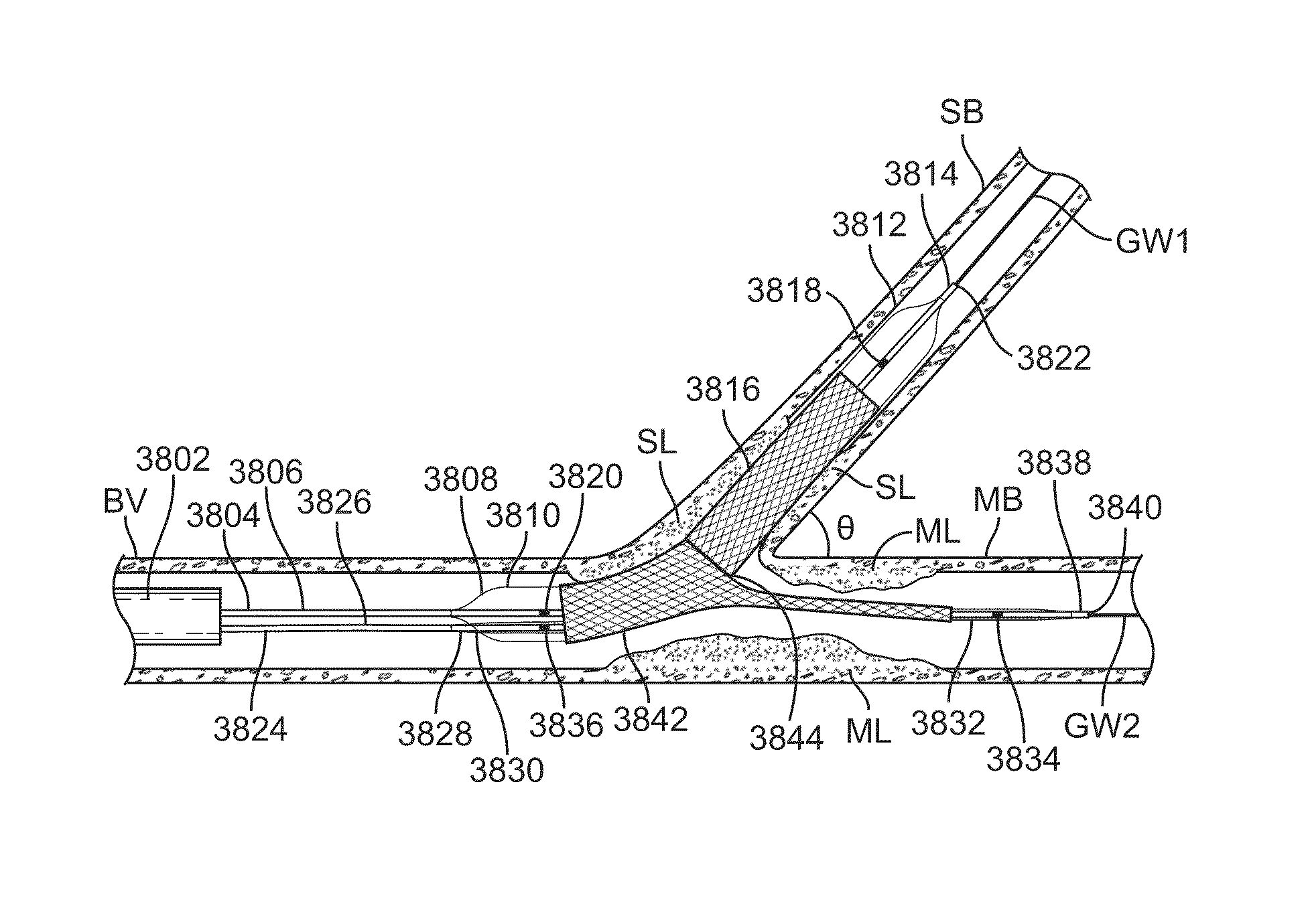
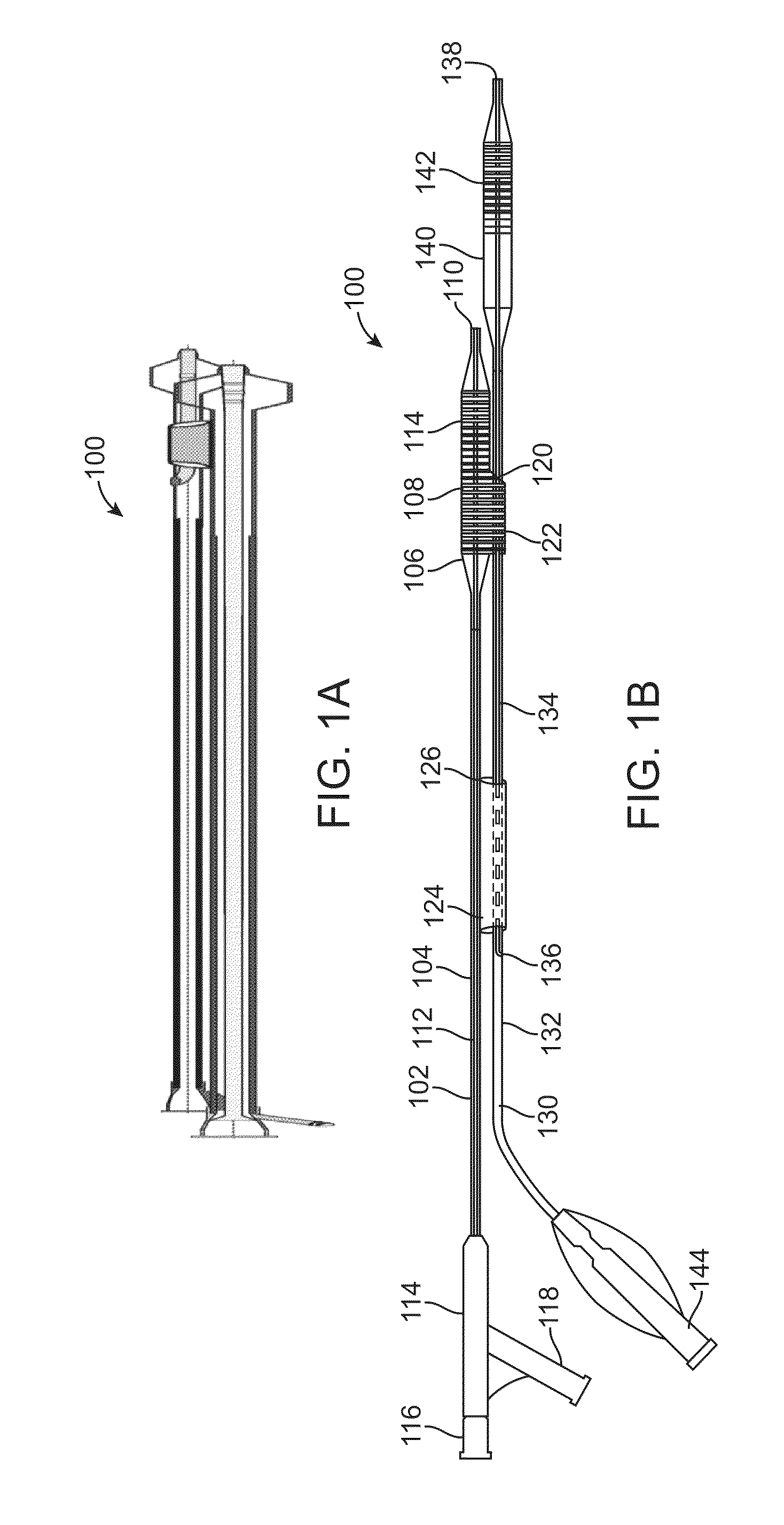
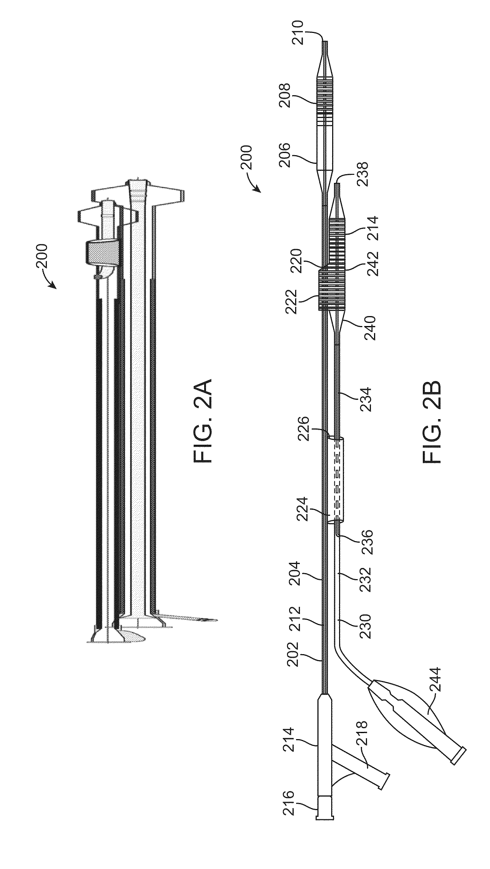
[0201]During animal testing, stent delivery systems similar to those illustrated in FIGS. 1A-1B, 2A-2B, 3A-3B, and 4A-4B were used to deliver a first stent into a side branch and a second stent into a main branch at a bifurcated vessel. After alignment of the proximal end of the side branch stent with the side hole of the main branch stent, the stents were radially expanded using methods described above. It was predicted that the stents would either overlap with one another, or the stent ends would butt up against one another, or a gap would exist between the two stents. However, an unexpected result was achieved. Under fluoroscopy, the proximal end of the side branch stent was observed to interdigitate with the side hole in the main branch, similar to FIG. 46A. This provided uniform and continuous scaffolding along the main branch across the bifurcation and into the side branch, without obstructing the ostium to the side branch.

[0202]Balloon Configurations:

[0203...


PUM


Abstract

A system for treating a bifurcation includes a first radially expandable stent and a second radially expandable stent. The first stent has a side hole and a plurality of lateral elements extending from the side hole. The second stent has a plurality of axial elements extending away from the proximal end of the second stent. The axial elements of the second stent interdigitate with the lateral elements of the first stent when both stents have been expanded.

Description

CROSS-REFERENCES TO RELATED APPLICATIONS[0001]The present application is a continuation in part of International PCT Application No. PCT / US2009 / 058505 filed Sep. 25, 2009 which claims the benefit of U.S. Provisional Patent Application No. 61 / 194,346 filed Sep. 25, 2008, the entire contents of each of which are incorporated herein by reference. The present application is also a non-provisional of, and claims the benefit of U.S. Provisional Patent Application No. 61 / 317,121, filed Mar. 24, 2010, the entire contents of which are incorporated herein by reference.[0002]The present application is related to U.S. patent application Ser. No. 13 / 071,149, filed the same day as the present application. The present application is also related to U.S. patent application Ser. Nos. 13 / 071,251; 13 / 071,239; 13 / 071,198; and 13 / 071,162; each filed on the same day as the present application, and each of which is incorporated herein by reference. The present application is also related to U.S. Provision...

Claims


Application Information

Patent Timeline
Patent Type & Authority Patents(United States)
IPC IPC(8): A61F2/954A61F2/06A61M25/10A61F2/958
CPCA61F2/954A61F2/958A61M2025/1079A61M2025/1045A61F2/86A61F2/856
Inventor BOURANG, HENRYKHORSANDI, MEHRAN
Owner ADVANCED BIFURCATION SYST
Why Eureka
Try Eureka