
Method for automatic yaw axis control for aircraft with mechanical flight controls

a flight control and automatic technology, applied in the direction of process and machine control, instruments, navigation instruments, etc., can solve the problems of imposing a heavy workload, causing passenger discomfort, excessive fuel consumption, and causing passengers to asymmetry, so as to reduce the workload of pilots, improve safety, and reduce the effect of risks

Active Publication Date: 2014-08-19
THALES SA
View PDF8 Cites 2 Cited by
  • Summary
  • Abstract
  • Description
  • Claims
  • Application Information

AI Technical Summary

Benefits of technology

The present invention provides an automatic yaw axis control method for aircraft that can simultaneously control the yaw actuator and the yaw trim actuator. This method can reduce the pilot workload, improve safety, enhance passenger comfort, and reduce fuel consumption of the aircraft by improving its symmetry.

Problems solved by technology

This induced asymmetry is uncomfortable for passengers and critical for the pilot, in particular in the event of failure of an engine.
This imposes a heavy workload, notably on jet or turbo aircraft and when changing engine operating conditions.
Moreover, it is difficult to ensure perfect symmetry of the aircraft, resulting in passenger discomfort and excess fuel consumption.
The risk of asymmetrical stalling is high during these critical flight phases.

Method used


Image

  • Method for automatic yaw axis control for aircraft with mechanical flight controls
  • Method for automatic yaw axis control for aircraft with mechanical flight controls
  • Method for automatic yaw axis control for aircraft with mechanical flight controls

Examples


Embodiment Construction

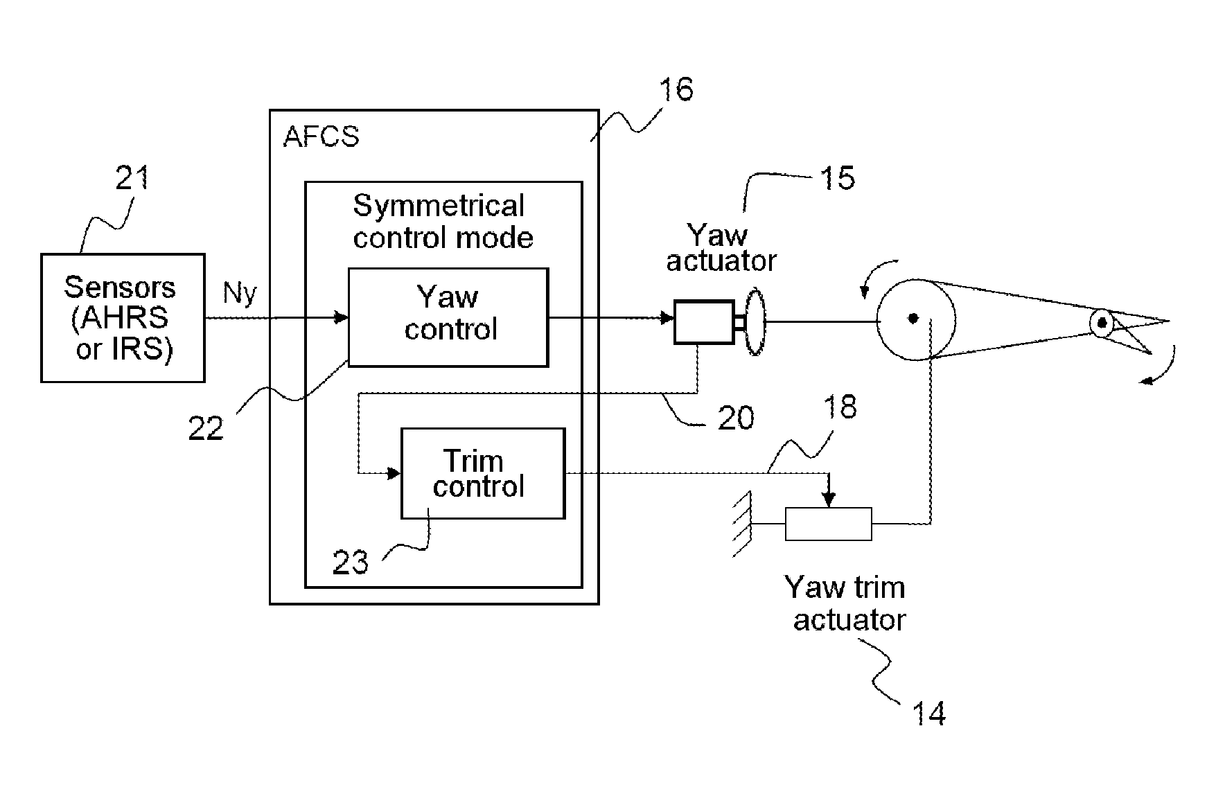
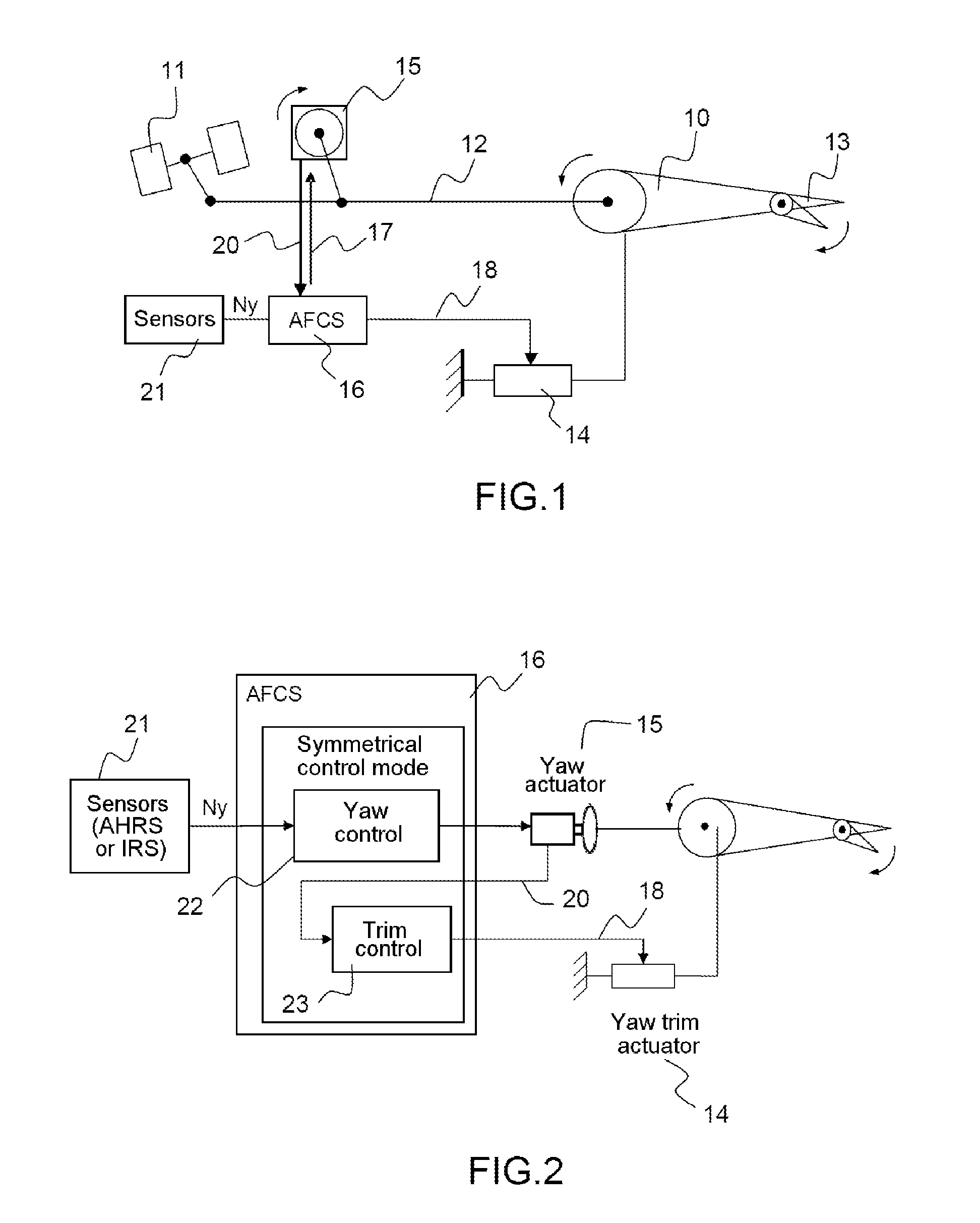
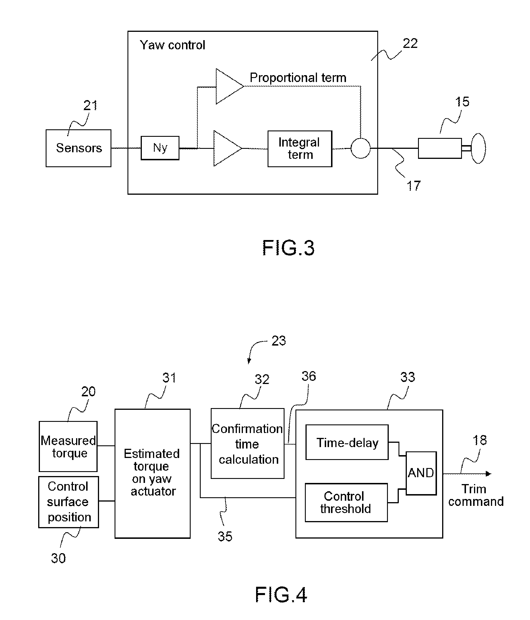
[0023]FIG. 1 represents the architecture of an aircraft with mechanical flight controls provided with an automatic yaw axis control system in accordance with the invention. An aircraft with mechanical flight controls includes a yaw control surface 10, for example on the vertical tail fin at the rear of the aircraft, which by its angular position controls the orientation of the aircraft about the yaw axis. The yaw control surface 10 can be controlled manually by the pilot by means of rudder pedals 11 situated in the cockpit and connected to the yaw control surface 10 by a system of cables 12. To compensate the effort exerted by the yaw control surface 10, a yaw trim control surface 13 also known as a compensator can be oriented by means of a yaw trim actuator 14. This is typically a control surface smaller than and mounted on the main yaw control surface 10. By orienting it, it is possible to generate a torque opposing the torque generated by orienting the main yaw control surface. T...


PUM


Abstract

A method for automatic yaw axis control in aircraft with mechanical controls, said aircraft including a yaw actuator to control orientation of a yaw control surface and deliver a measured value of the torque on the control surface, a yaw trim actuator driving movement of a yaw trim control surface limiting the force applied by the yaw actuator to orient the yaw control surface, and sensors supplying an estimate of a lateral yaw force, includes calculating a setpoint value for the position of the yaw control surface determined by the estimated lateral force, an estimated torque of the yaw actuator determined by the measured value of the torque of the yaw actuator and a measured position of the yaw control surface, the estimated torque calculated having a lower oscillation dynamic range than the measured torque, and a trim command for activating / deactivating the yaw trim actuator determined by the estimated torque.

Description

CROSS-REFERENCE TO RELATED APPLICATION[0001]This application claims priority to foreign French patent application No. FR 1201716 , filed on Jun. 15, 2012, the disclosure of which is incorporated by reference in its entirety.FIELD OF THE INVENTION[0002]The present invention lies in the field of automatic aircraft control methods. To be more precise, it relates to an automatic control method for an aircraft with mechanical flight controls adapted to control lateral forces by automatic aircraft yaw axis control.BACKGROUND[0003]In an aircraft with mechanical flight controls, the pilot manoeuvres the machine by means of controls in the cockpit, such as the yoke or rudder pedals, connected mechanically, typically by cables, to a set of control surfaces adapted to modify the trajectory of the machine. The pilot generally controls yaw by means of control surfaces on the axial vertical tail fin controlled by the rudder pedals. Lateral acceleration, generally denoted Ny, generated for example...

Claims


Application Information

Patent Timeline
Patent Type & Authority Patents(United States)
IPC IPC(8): B64C13/16B64C13/18B64C13/30
CPCB64C13/16B64C13/18B64C13/30G05D1/0808
Inventor MERET, YANNICKBONNAFOUX, ARNAUDSIMON, CHRISTOPHE
Owner THALES SA
Learn More