Navigation system using locally augmented GPS

a local augmented and navigation system technology, applied in the field of navigation systems using local augmented gps, can solve the problems of inability to accurately calculate the position, high cost of purchasing and maintaining a complete aircraft navigation system, and complex structure,

Inactive Publication Date: 2004-06-24
THE BOARD OF RGT UNIV OF OKLAHOMA
View PDF3 Cites 38 Cited by
  • Summary
  • Abstract
  • Description
  • Claims
  • Application Information

AI Technical Summary

Problems solved by technology

Consequently the purchase and maintenance of a complete aircraft navigation system has been extremely expensive and complex.
Because the travel time is a calculated value, it is susceptible to several different types of errors.
This is very important because if the receiver's clock and the satellites clock are not synchronized, the calculated position will be wrong.
The greatest hurdle that the global positioning system must overcome is an inability to provide quality suitable for primary-means aircraft navigation.
These downfalls are a result of several different error sources.
The atomic clocks that are used in satellites are extremely accurate; however, they still have small deviations that can manifest in the form of calculation errors.
G.P.S. receivers do not use atomic clocks and are therefore even more susceptible to timing errors.
This uncertainty in position can lead to errors in the receiver's position calculations.
Unfortunately, radio waves are susceptible to many types of interference.
These electrons appear opaque to the radio waves and therefore cause the waves to deflect.
The troposphere, the layer of the atmosphere from ground level to approximately 8 km above the earth's surface, is also a source of interference.
This interference is a result of variations in the composition of the medium through which the radio waves are traveling.
Both of these layers cause a deviation in the radio waves' paths, which introduces a delay in transmission time and can lead to erroneous distance calculations...

Method used


Image

  • Navigation system using locally augmented GPS
  • Navigation system using locally augmented GPS
  • Navigation system using locally augmented GPS

Examples


Embodiment Construction

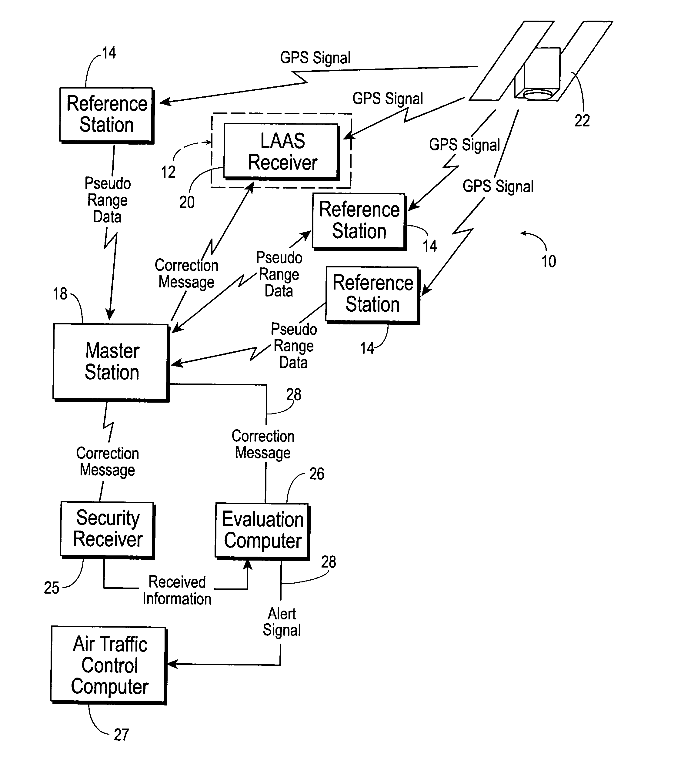
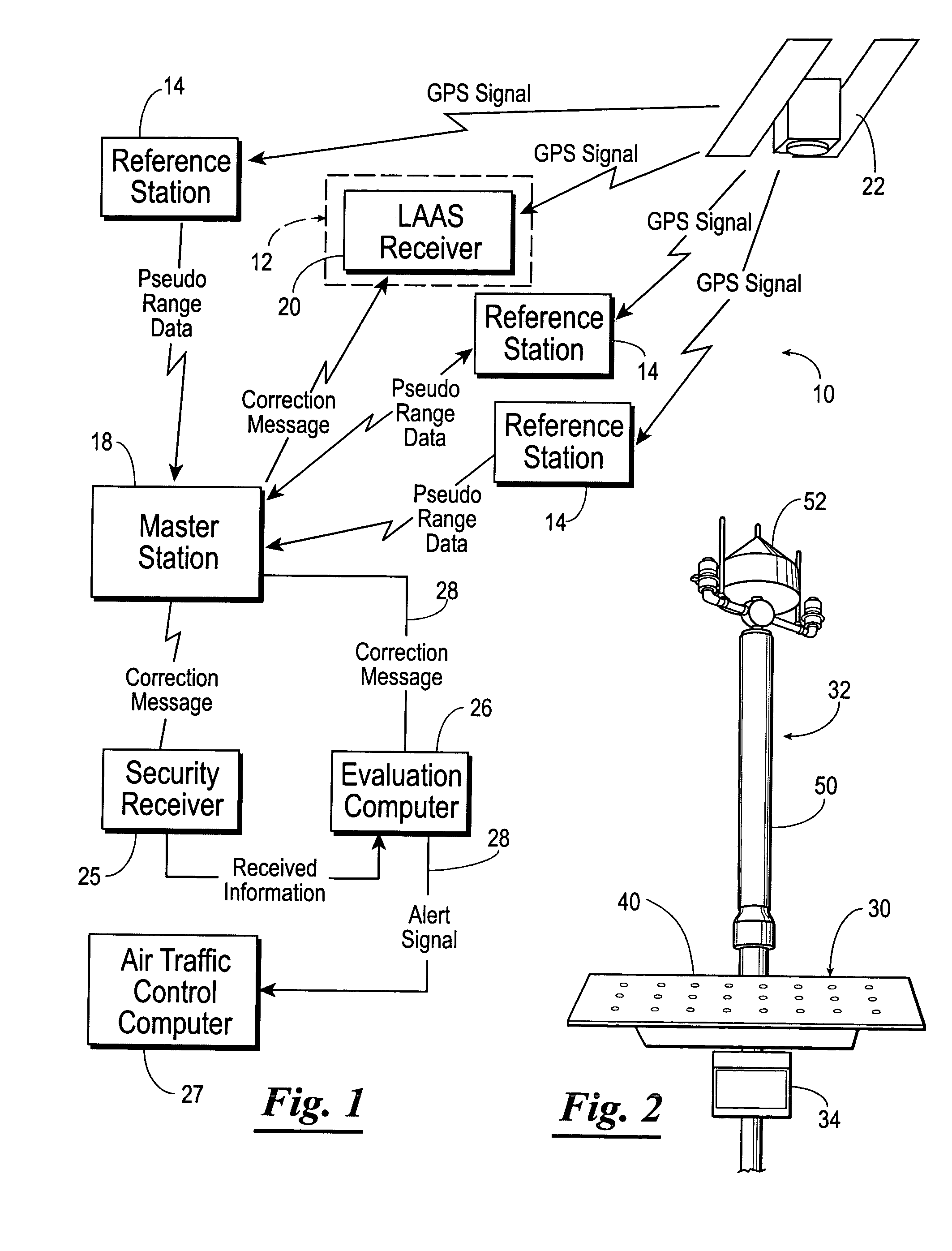
[0042] Referring now to FIG. 1, shown therein and designated by a reference numeral 10 is a navigation system constructed in accordance with the present invention. The navigation system 10 uses locally augmented GPS and does not require significant support infrastructure, such as power and communication lines. Although the navigation system 10 is described herein as a navigation system for an airport landing system, it should be understood that the navigation system 10 can be used for other types of navigation, such as nautical navigation, vehicular navigation or navigation of robots or other types of equipment or machinery. For example, the navigation system 10 can be used for navigating barges or other types of ships. The navigation system 10 is especially useful in high-volume traffic areas.

[0043] Set forth hereinafter is one specific embodiment of the present invention. However, it should be understood that the present invention is not limited to this specific embodiment. The na...


PUM


Abstract

A local area augmentation navigation system for determining the location of an object using differential GPS. The system does not require any significant power or communication infrastructure. The system includes at least three reference stations, a master station and a LAAS receiver. The at least three reference stations are located in close proximity to each other and at known locations. Each of the reference stations receive a GPS signal from a GPS constellation and collect and output via a wireless transceiver the pseudo-range data from the GPS signal. The master station is positioned in close proximity to the reference stations and receives the pseudo-range data from the reference stations. The master station forms a correction message from the pseudo-range data and the known locations of the reference stations. The master station broadcasts the correction message within a specified area. The LAAS receiver is positioned within the specified area and receives the correction message broadcast by the master station as well as a GPS signal from the GPS constellation. The LAAS receiver calculates the location of the LAAS receiver with the correction message and the GPS signal.

Description

[0001] The present patent application claims priority to the provisional patent application identified by U.S. serial No. 60 / 413,845, entitled AIRPORT LANDING SYSTEM USING LOCALLY AUGMENTED GPS filed on Sep. 25, 2002, the entire content of which is hereby incorporated herein by reference.BACKGROUND OF INVENTION[0003] In today's fast-paced society, travel has become an integral part of life in both business and pleasure. Among the many forms of travel, air travel has considerably increased in recent years to become one of the main staples. In 1995, the air travel system moved 555 million passengers. The Federal Aviation Administration forecasts predicted 800 million passengers per year will be flying in less than a decade, with more than one billion flying annually by 2010. This rapid increase has raised concerns about the ability of present-day navigational systems to provide the precise positional awareness that is essential to manage the increased volume of planes and passengers.[...

Claims


Application Information

Patent Timeline
IPC IPC(8): G01S1/00G01S5/00G01S19/38G01S5/14G01S19/05G01S19/07G01S19/11G01S19/21G01S19/29G01S19/41G01S19/46
CPCG01S5/009G01S19/07G01S19/41G01S19/215G01S19/23G01S19/15
Inventor FAGAN, JOHN E.WEN, HENGQUINPENDERGRAFT, RICK
Owner THE BOARD OF RGT UNIV OF OKLAHOMA
Why Eureka
Try Eureka