Automated method for quality control and quality assurance of sized bridging material

a technology of bridging material and automatic method, which is applied in the field of drilling fluids, can solve the problems of destroying the desired fluid properties and bridging abilities, affecting the drilling operation, and affecting the flow rate of drilling fluid into the reservoir, so as to reduce the formation damage

Active Publication Date: 2014-08-26
SAUDI ARABIAN OIL CO
View PDF23 Cites 0 Cited by
  • Summary
  • Abstract
  • Description
  • Claims
  • Application Information

AI Technical Summary

Benefits of technology

[0016]These and other problems are generally solved or circumvented, and technical advantages are generally achieved, by preferred embodiments of the present invention that provide an improved laboratory method for evaluating the durability of sized bridging materials used in the formulation of drill-in fluid to eliminate or minimize formation damage.
[0020]An advantage of a preferred embodiment is that it provides a testing method to determine the relative strength of sized bridging materials in simulated wellbore conditions. The testing method provides a metric that allows operators to select the appropriate sized bridging materials. By using this metric to select an appropriate sized bridging material, operators decrease additions of sized bridging material to the drilling mud to maintain the desired particle distribution during wellbore operations. This reduces mud treatment and management cost. Using the metric to select an appropriate sized bridging material will also increase drilling efficiency and decrease the scope of formation damage induced by the particles of the sized bridging materials in the drilling mud. This also reduces spurt loss and internal mudcake buildup in the vicinity of the wellbore, aiding the cleaning of the wellbore before completion. The formation of good quality mudcake on the borehole wall will reduce the filtrate loss and cause minimum changes to oil relative permeability in the near wellbore reservoir formation. Thus, pore plugging by fines migration, flow reduction due to relative permeability change, and poro-perm characteristics alteration due to internal mudcake formation will be eliminated or reduced.

Problems solved by technology

The effectiveness of bridging materials depends on their structural durability, as they are subject to damage due to extreme conditions during the drilling operation (i.e., “downhole conditions”).
When the bridging materials decompose into smaller and finer particles, the intended distribution scheme is lost, destroying the desired fluid properties and bridging abilities.
The smaller, finer particles resulting from the decomposition of bridging materials can also harm the drilling operation.
For example, the loss of the drilling fluid's bridging ability may result in the migration of drilling fluids into the reservoir.
And after migrating into the formation, the bridging materials, including the fine particles created when bridging materials decompose, can create deposits that damage the reservoir and significantly reduce the production capability of a well.
Although properly sized bridging materials are very useful in plugging and sealing fractures and openings in a borehole wall to create a tight and low-permeability mud-cake, failure to maintain the intended size distribution while drilling may be a severe cause of near-wellbore formation damage.
However, there is no industry method or standard test method to monitor the PSD while drilling or to screen and evaluate different bridging materials as a part of quality control / assurance procedures or as part of selecting optimal bridging materials (i.e., materials with an optimal durability index).
Tests conducted using a reservoir core and a dynamic mud flow loop at stimulated reservoir conditions resulted in 20% loss in return permeability in the presence of the size optimized drill-in fluid.
That process provides suitable quality control and quality assurance for coarse and medium sized bridging materials; however, the process is limited with respect to quality control and quality assurance for fine sized bridging materials.
In addition, the process disclosed above requires significant human interaction to conduct both the sieving and drying processes needed to accurately assess the sized bridging materials.
The significant human interaction could negatively effect the results of the process.
Still further, these human labor processes add significantly to the length of the quality control and quality assurance process.

Method used


Image

  • Automated method for quality control and quality assurance of sized bridging material
  • Automated method for quality control and quality assurance of sized bridging material
  • Automated method for quality control and quality assurance of sized bridging material

Examples


Embodiment Construction

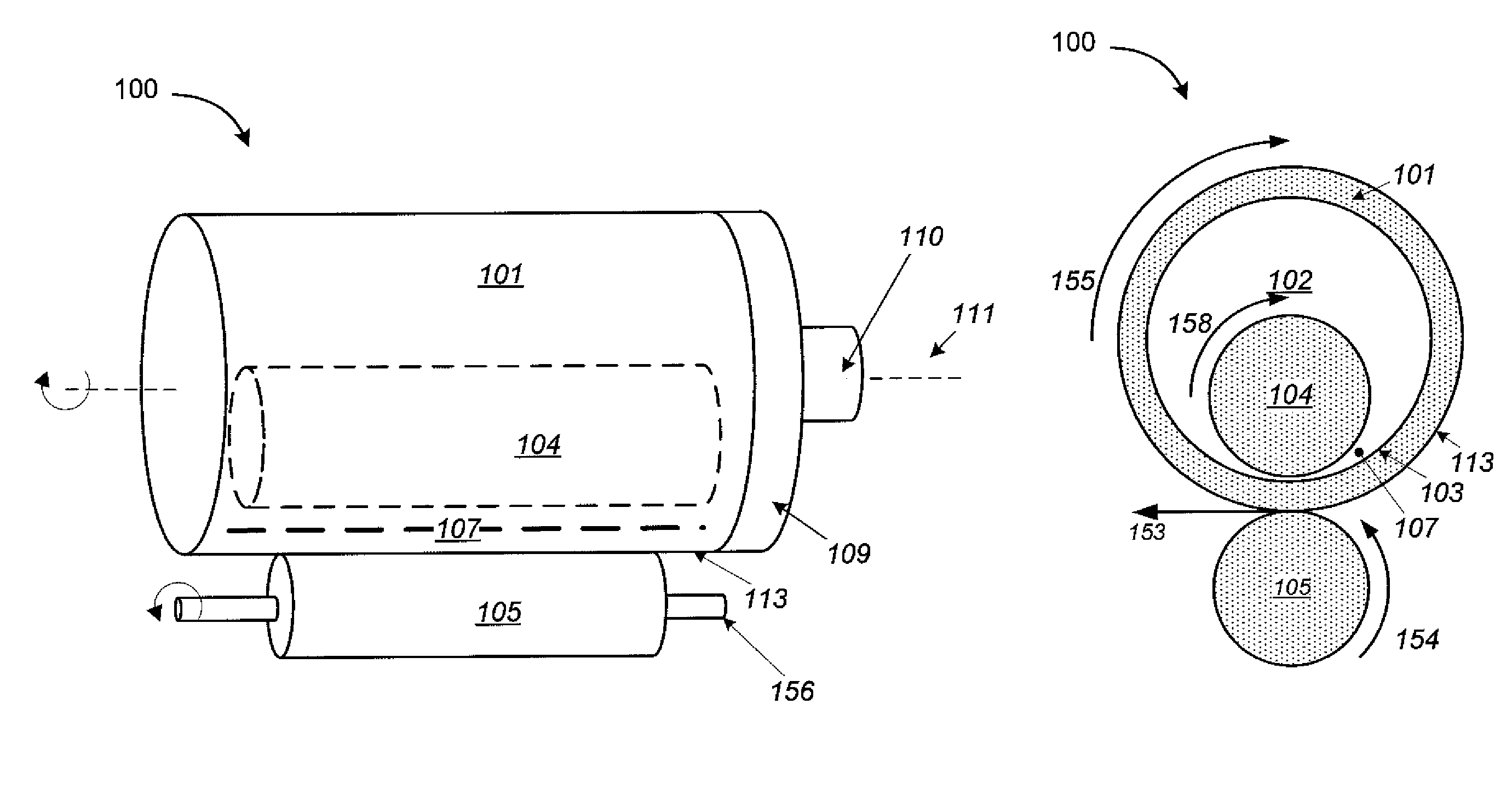
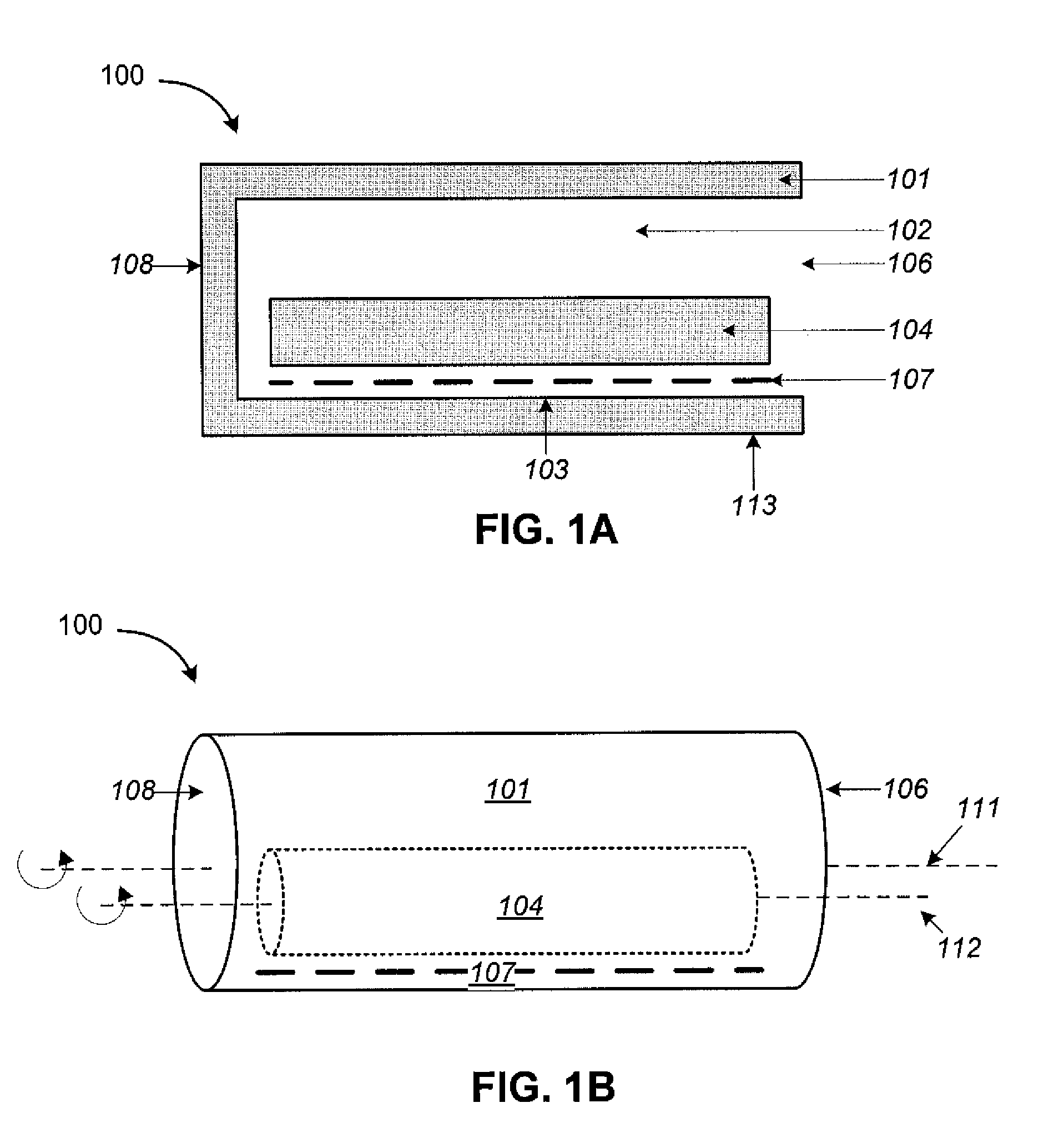
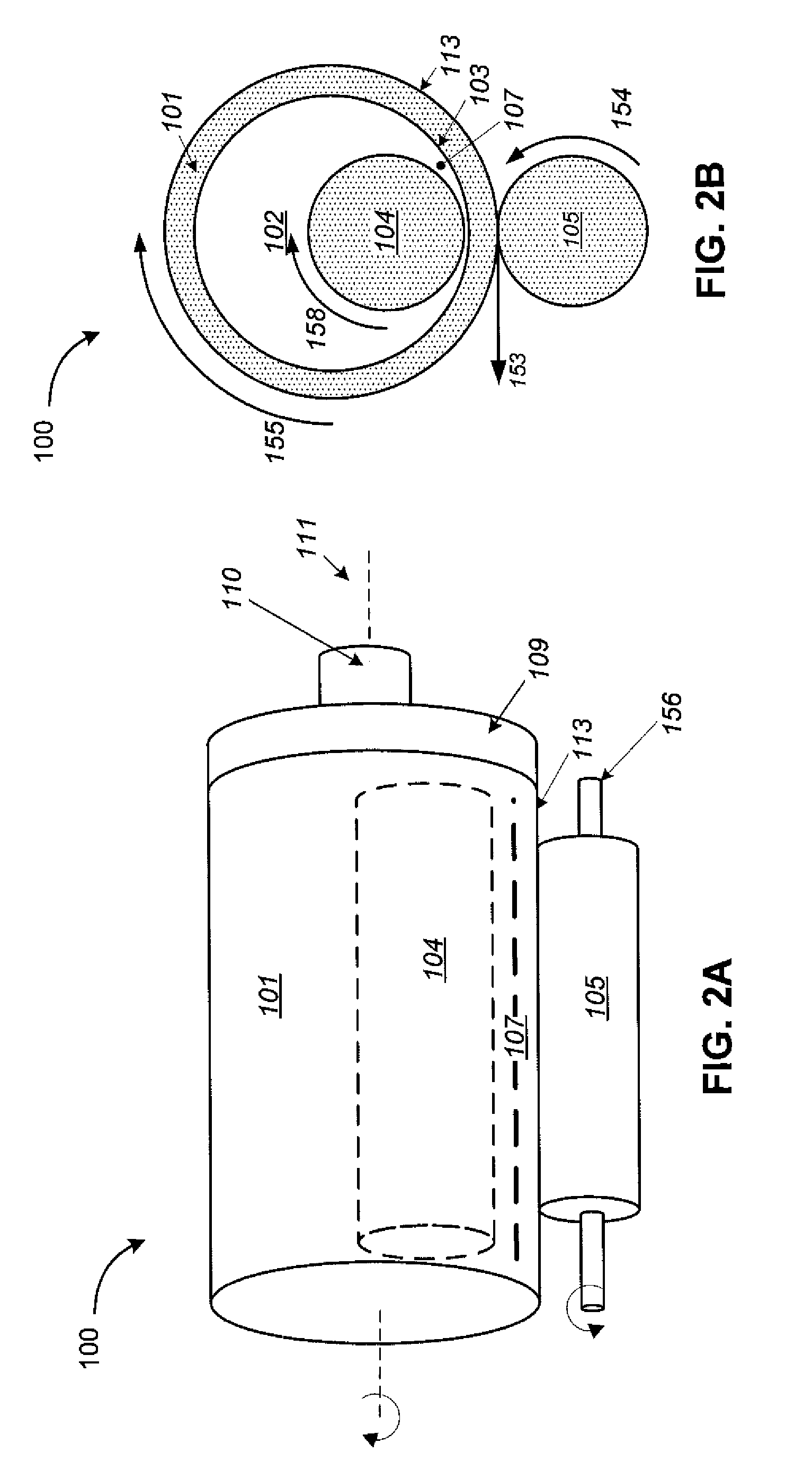
[0036]The present invention will now be described more fully hereinafter with reference to the accompanying drawings which illustrate embodiments of the invention. This invention may, however, be embodied in many different forms and should not be construed as limited to the illustrated embodiments set forth herein. Rather, these embodiments are provided so that this disclosure will be thorough and complete, and will fully convey the scope of the invention to those skilled in the art. Like numbers refer to like elements throughout, and the prime notation, if used, indicates similar elements in alternative embodiments.

[0037]In the following discussion, numerous specific details are set forth to provide a thorough understanding of the present invention. However, it will be obvious to those skilled in the art that the present invention may be practiced without such specific details. Additionally, for the most part, details concerning sized bridging material selection, drill-in fluid use...


PUM

PropertyMeasurementUnit
temperatureaaaaaaaaaa
diameteraaaaaaaaaa
diameteraaaaaaaaaa

Abstract

A method for quality control and quality assurance of sized bridging materials rotates a control sample having a fluid portion and a solids portion of sized bridging materials in a tubular container for a predetermined period of time. The control sample is then analyzed in a laser particle size analyzer to determine a particle size distribution for the control sample. A wet grinding sample having a fluid portion and a solids portion of the sized bridging materials is then rotated in the tubular container with a loose cylinder rod for a predetermined time to simulate borehole conditions. The wet grinding sample is then analyzed in the laser particle size analyzer to determine a particle size distribution for the wet grinding sample. The two particle size distributions are used to define a shift factor that represents the relative strength of the sized bridging materials.

Description

[0001]This application claims priority to and the benefit of co-pending U.S. Provisional Application No. 61 / 542,606, by Amanullah et al., filed on Oct. 3, 2011, entitled “Improved and Automated Method for Quality Control and Quality Assurance of Sized Bridging Material,” which application is incorporated herein by reference.BACKGROUND OF THE INVENTION[0002]1. Field of the Invention[0003]The present invention relates in general to drill-in fluids used in oil and gas drilling and, in particular, to a laboratory method for evaluating the durability of sized bridging materials used in the formulation of drill-in fluid to eliminate or minimize formation damage.[0004]2. Brief Description of Related Art[0005]A drill-in fluid is a special type of fluid formulated for oil and gas drilling. The drill-in fluid is pumped into a borehole while drilling through porous and permeable subsurface rock formations that store and transmit oil and gas, i.e., a reservoir. The drill-in fluid contains solid...

Claims


Application Information

Patent Timeline
Patent Type & Authority Patents(United States)
IPC IPC(8): G01N15/00
CPCG01N33/2823C09K8/03C09K2208/18G01N3/56G01N15/0211G01N2203/0087G01N2203/0641
Inventor AMANULLAH, MD.ALLEN, JOHN T.KILANI, MOHAMMED H.
Owner SAUDI ARABIAN OIL CO
Why Eureka
Try Eureka