Vented insulation unit and system

Pending Publication Date: 2022-01-20
SCHERRER EDWARD G +1
View PDF0 Cites 0 Cited by
  • Summary
  • Abstract
  • Description
  • Claims
  • Application Information

AI Technical Summary

Benefits of technology

[0010]The present invention is directed to an insulation unit and a wall insulation system, and in particular to a wall finishing system suitable for wood or steel frame walls, concrete, CMU, masonry and other similar wall construction. The present invention utilizes foam insulating units that are used i

Problems solved by technology

Although such systems have proven to be suitable and often provide satisfactory finishing, such systems have several drawbacks.
Conventional mounting of studs to a concrete wall is difficult and has weaknesses.
The studs may warp or twist and may cause the nails to protrude back through drywall.
The wood studs are prone to mold, moisture damage and rot that require an additional vapor barrier.
Steel studs are an alternative, but generally prove difficult for the average homeowner to install, require special mounting and suffer from high thermal conductivity through the depth of the wall and may also rust and/or corrode.
Fiberglass insulation is also susceptible to water damage and mold if moisture is present.
The thickness required for adequate insulation may decrease the overall size of the room due to the added depth of the wall.
Fiberglass insulation is difficult to handle and requires special gloves and a respirator.
Common stud and rolled fiberglas

Method used


Image

  • Vented insulation unit and system
  • Vented insulation unit and system
  • Vented insulation unit and system

Examples


Embodiment Construction

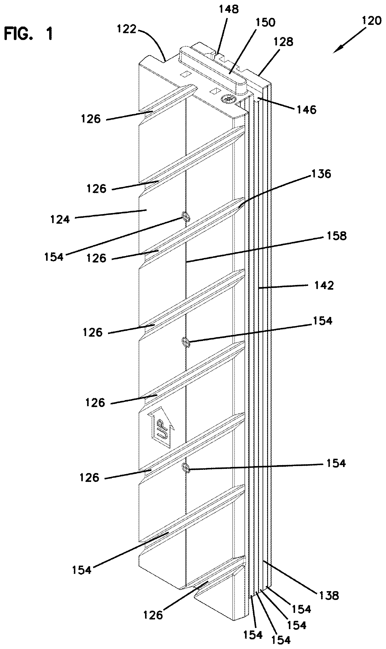
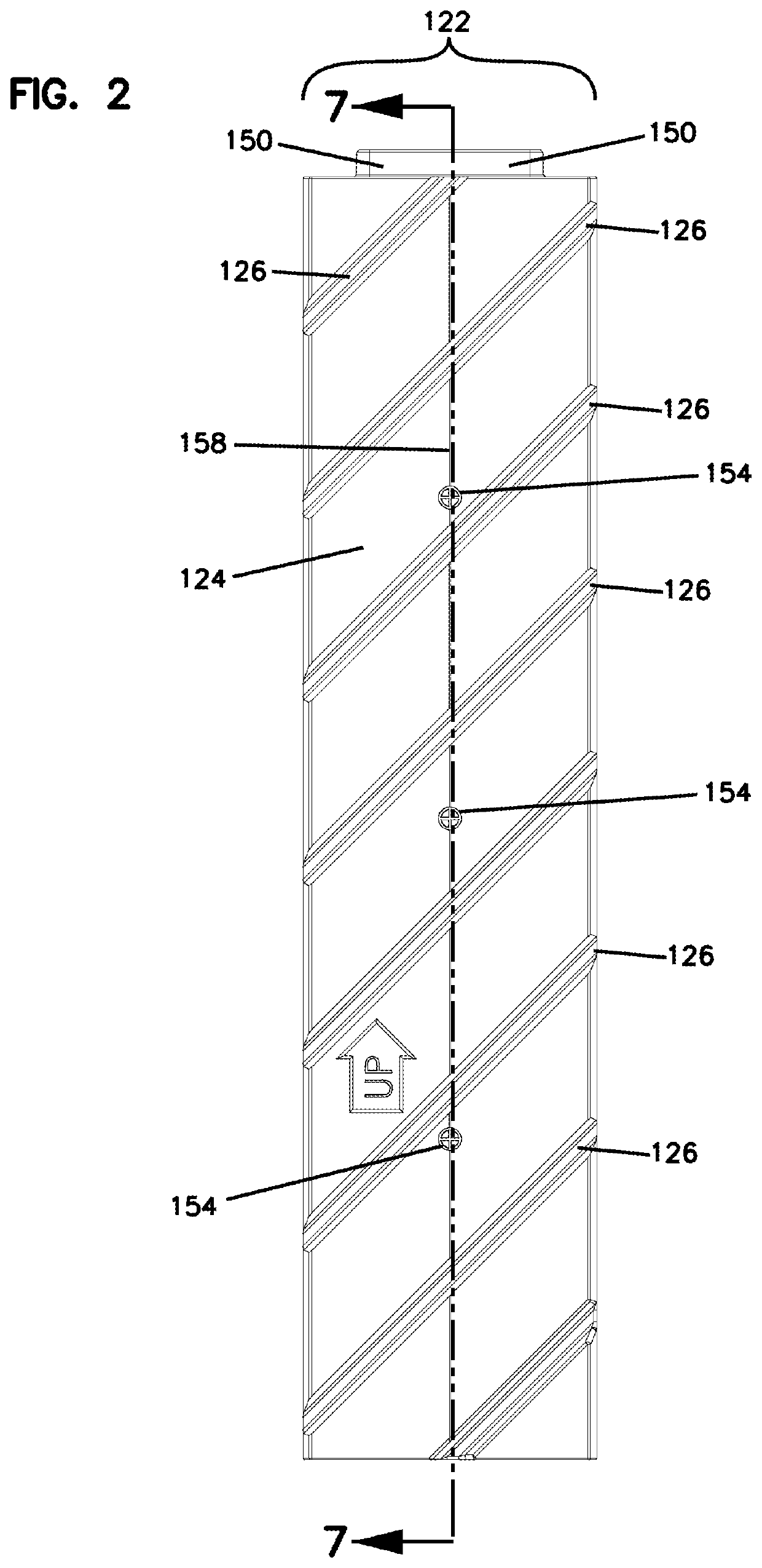
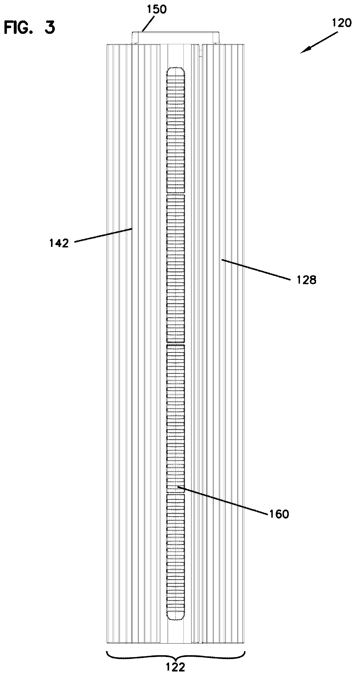
[0038]Referring now to FIGS. 1-7, there is shown an insulated mounting unit (120) utilized in a wall system (100) shown in FIGS. 13-18, as explained hereinafter. Referring again to FIGS. 1-7, the insulated mounting unit (120) includes an insulating molded foam portion (122) with a stud element (160) embedded within the foam portion (122). The stud (160) extends longitudinally and provides support and mounting surfaces. The insulation unit (120) includes a widened first portion includes a first face (124) having parallel angled channels formed along the first face. The first face (124) also includes mounting marks (154) providing an indication of where fasteners may be attached to extend through the embedded stud element (160). A narrower second portion includes an opposite face (128) with ridges (142) that form gaps to provide capillary action if needed. The first face (124) is wider than the second face (128) and forms shoulder surfaces (132) and (134) that receive conventional pla...


PUM


Abstract

A wall insulation system includes a plurality of insulation elements extending along a longitudinal direction. First insulation elements include a first portion proximate a second portion, the first portion having a width greater than the second portion, the first portion having a first face, the first face having grooves formed into the first face. The grooves extend obliquely to the longitudinal direction. A longitudinally extending mounting member is embedded in the first insulating element.

Description

[0001]This application is being filed on Dec. 6, 2019, as a PCT International Patent application and claims priority to U.S. Provisional patent application Ser. No. 62 / 776,980, filed Dec. 7, 2018, the entire disclosure of which is incorporated by reference in its entirety.BACKGROUND OF THE INVENTIONField of the Invention[0002]The present invention is directed to an insulation system and in particular to a finishing system having insulating assemblies fitted together for mounting onto walls or other building structures and providing insulation, venting and moisture drainage.Description of the Prior Art[0003]Wall systems for conventional frame type construction, basements and other applications wherein a masonry, concrete modular unit (CMU) or poured concrete wall are often used in conjunction with traditional wood framed construction with studs and with rolled fiberglass insulation placed against the concrete block or other masonry between the studs. Such construction systems are wel...

Claims


Application Information

Patent Timeline
IPC IPC(8): E04B1/76E04F13/075E04F13/08
CPCE04B1/7675E04F13/075E04F2290/04E04F13/0866E04F13/0878E04F13/0803E04B1/7612
Inventor SCHERRER, EDWARD G.SCHERRER, ANDREW ROBERT
Owner SCHERRER EDWARD G
Why Eureka
Try Eureka