
Inkjet printer and control method for inkjet printer

a control method and inkjet printer technology, applied in the field of inkjet printers, can solve the problems of high probability of inappropriate portions being irradiated with uv, loss of ability to eject in proper fashion, and inability to control the dose of irradiated uv

Inactive Publication Date: 2014-08-26
SEIKO EPSON CORP
View PDF10 Cites 0 Cited by
  • Summary
  • Abstract
  • Description
  • Claims
  • Application Information

AI Technical Summary

Benefits of technology

The patent text describes a device that controls the movement of a scanning part that ejects curing light. The device detects the speed of the scanning part and adjusts the output of its drive source accordingly. If the scanning part is constantly moving, the device will increase the output of the drive source to ensure that the curing-light-emitting part is always in a state of emission. Conversely, if the speed of the scanning part is decreasing, the device will decrease the output of the drive source to prevent unnecessary activation of the curing light. This ensures that the device control is efficient and effective in controlling the movement of the scanning part.

Problems solved by technology

For example, if the vicinity of the ejection ports of the inkjet head is irradiated with the curing light, curing of the liquid may proceed inside the ejection ports, resulting in a loss of ability to eject in proper fashion.
However, with the device or method disclosed in Japanese Patent No. 3855724, in a case in which a malfunction has arisen in the linear encoder, UV irradiation will be carried out based on erroneous position information about the printing section, therefore leading to the problem of a high probability of inappropriate portions being irradiated with UV as well.
Additionally, in a case in which a malfunction has arisen in the mover device of the UV irradiation means, the moving speed of the UV irradiation means with respect to the object being irradiated is inappropriate, causing the positions being irradiated to be irradiated with UV for an inappropriate time, leading to the problem of an inappropriate dose of irradiated UV.
Particularly where the same given portion continues to be irradiated with curing light, a rise in temperature or the like caused by excessive irradiation with curing light has led to the problem of a high probability of damage to the printing medium.
In a case in which a malfunction has arisen in the relative scanning part, the output of the drive source is greater than normal, due to the excessive load on the drive source.

Method used


Image

  • Inkjet printer and control method for inkjet printer
  • Inkjet printer and control method for inkjet printer
  • Inkjet printer and control method for inkjet printer

Examples


first modification example

[0156]In the aforedescribed embodiment, the ultraviolet irradiation time for which the area irradiated with ultraviolet is the UV irradiation area 294 begins when the UV LEDs 96 turn ON at time T21 which follows time T2 by the ON delay time t1. The ultraviolet irradiation time for which the area irradiated with ultraviolet is the UV irradiation area 296 begins when the UV LEDs 96 turn ON at time T2; and at a time T51 after the set irradiation time interval t2 following turning ON, the UV LEDs 96 are turned to OFF. However, the ultraviolet irradiation time may be an ultraviolet irradiation time having as the ON time thereof a point in time following elapse of an ON delay time subsequent to a reference time, and having as the OFF time a point in time following elapse of a predetermined time subsequent to the ON time. Alternatively, the ultraviolet irradiation time may be an ultraviolet irradiation time having as the ON time thereof a point in time following elapse of an ON delay time ...

second modification example

[0157]In the aforedescribed embodiment, the ultraviolet irradiation time for which the area irradiated with ultraviolet is the UV irradiation area 294 starts by turning the UV LEDs 96 to ON at time T21 which follows time T2 by the ON delay time t1. The time T2 is the point in time that the current value of the drive current of the drive motor 67 is equal to or greater than the irradiation boundary value A1, and the irradiation boundary value A1 is set to a value that is slightly lower than the drive current value observed when the carriage unit 22 is being scanned at the constant scanning speed VC. However, the starting point of the ON delay time may be, for example, the point in time of startup of the drive motor 67. Specifically, the first output value may be set to the smallest possible value within the range detectable by the drive output detecting part.

third modification example

[0158]In the aforedescribed embodiment, the ultraviolet irradiation time for which the area irradiated with ultraviolet is the UV irradiation area 296 starts by turning the UV LEDs 96 to ON at time T2; and at a time T51 after the set irradiation time interval t2 following turning ON, the UV LEDs 96 are turned to OFF. The time T2 is the point in time that the current value of the drive current of the drive motor 67 is equal to or greater than the irradiation boundary value A1, and the irradiation boundary value A1 is set to a value that is slightly lower than the drive current value observed when the carriage unit 22 is being scanned at the constant scanning speed VC. However, the starting point of the predetermined time until the curing-light-emitting part turns OFF may be, for example, the point in time of startup of the drive motor 67. Specifically, the first output value may be set to the smallest possible value within the range detectable by the drive output detecting part.


PUM


Abstract

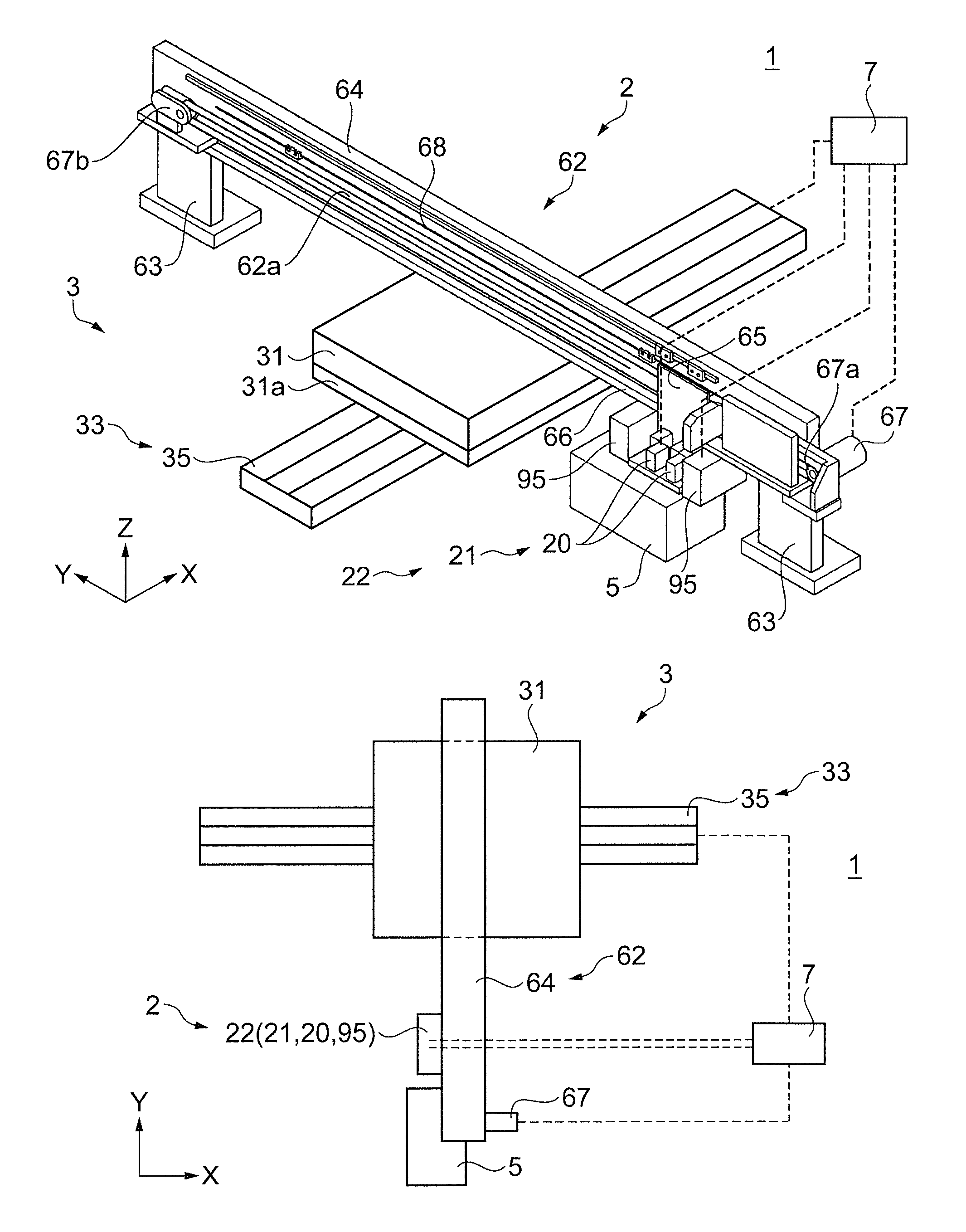
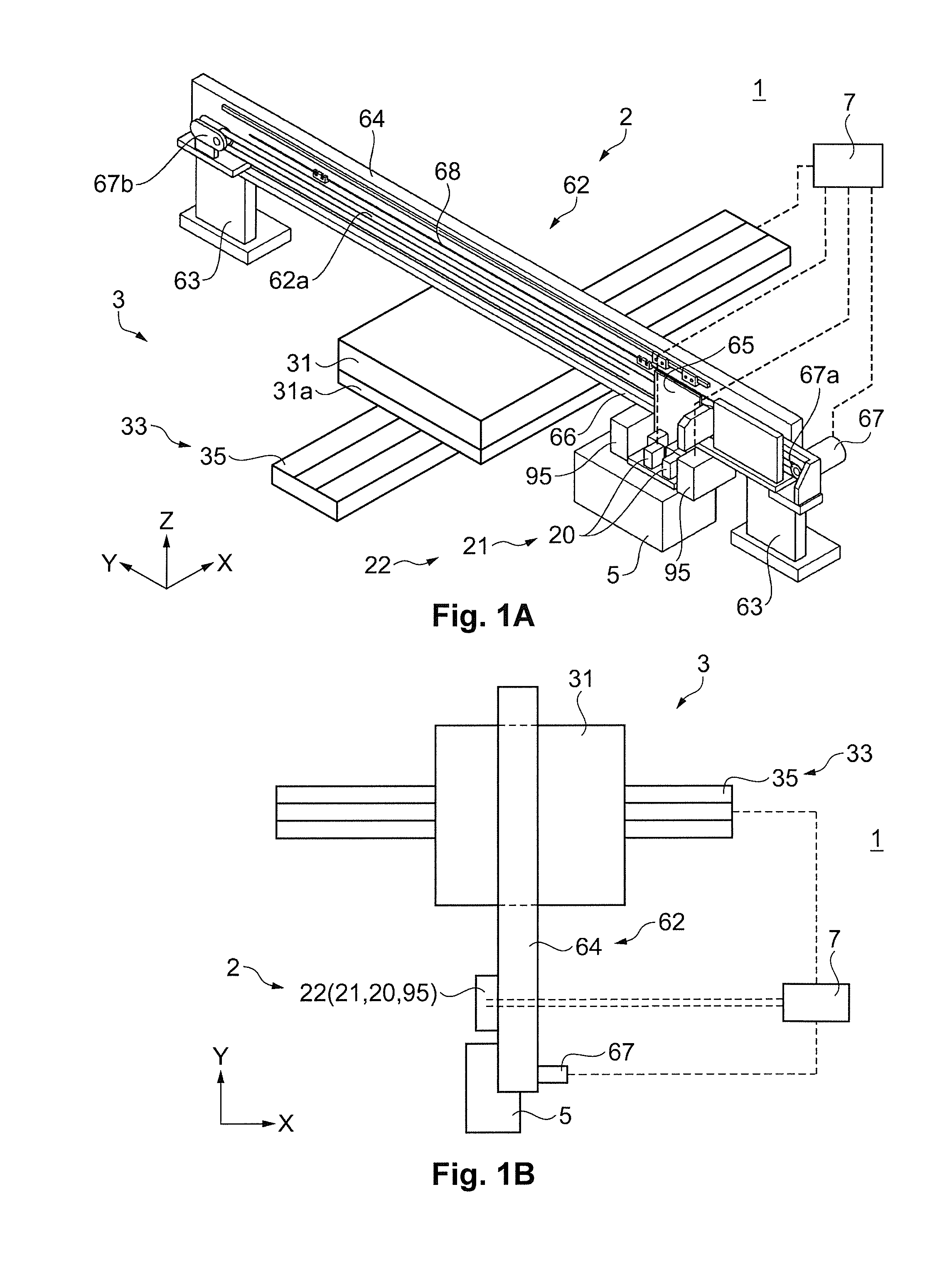
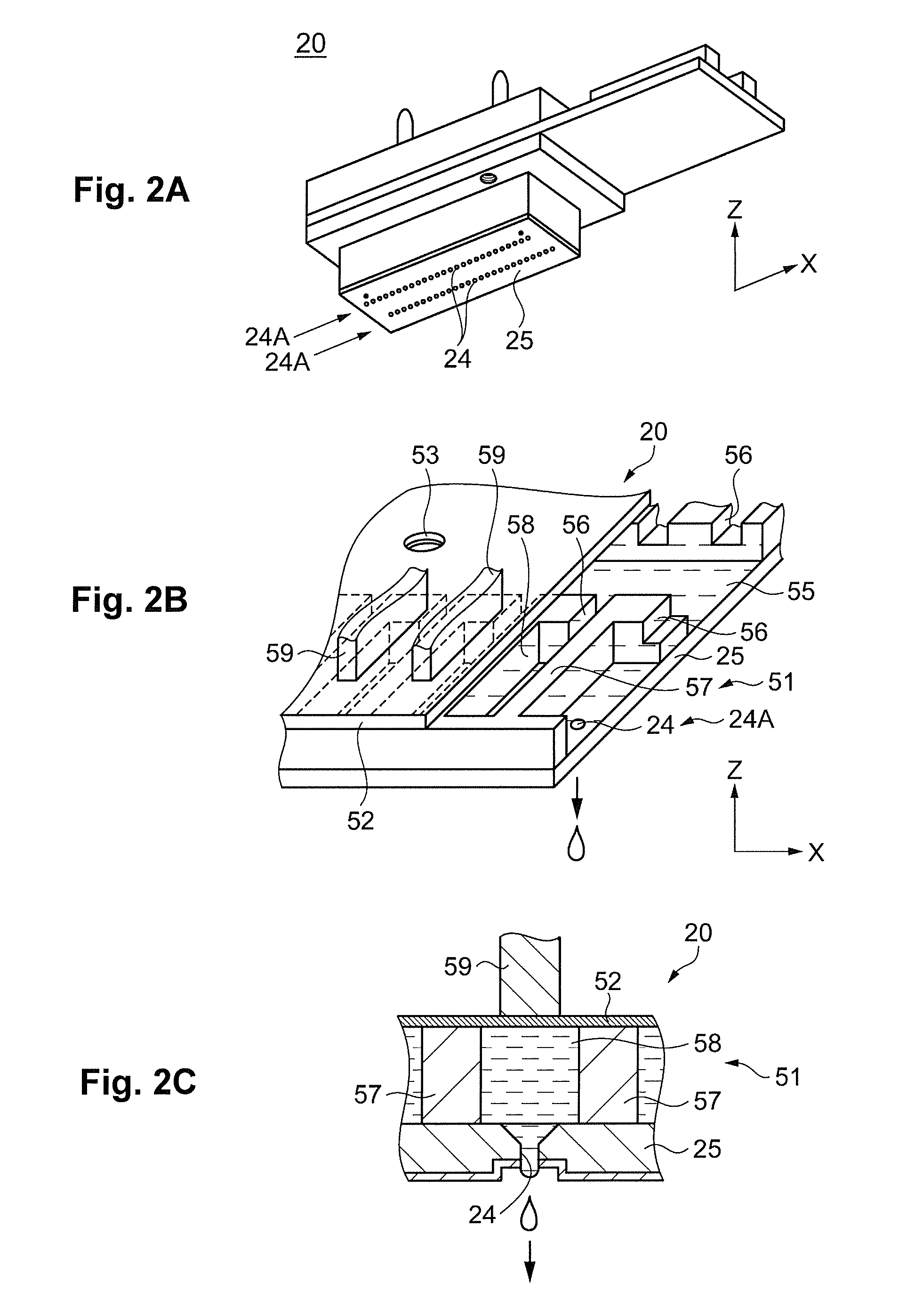
A inkjet printer includes an ejection head, a curing-light-emitting part, a head retaining part, a relative scanning part, a drive output detecting part, and a curing-light-emission-control part. The ejection head ejects a photocuring liquid onto a printing medium retained by a medium retaining part. The curing-light-emitting part emits curing light onto the printing medium. The head retaining part retains the ejection head and the curing light emitting part. The relative scanning part performs relative movement of the head retaining part and the medium retaining part. The drive output detecting part detects an output of a drive source of the relative scanning part. The curing-light-emission-control part controls the curing-light-emitting part based on a detection result from the drive output detecting part.

Description

CROSS-REFERENCE TO RELATED APPLICATIONS[0001]This application claims priority to Japanese Patent Application No. 2011-075803 filed on Mar. 30, 2011. The entire disclosure of Japanese Patent Application No. 2011-075803 is hereby incorporated herein by reference.BACKGROUND[0002]1. Technical Field[0003]The present invention relates to an inkjet printer for printing images onto a printing medium, by ejecting droplets of a liquid so as to cause them to land on the printing medium and dispose the liquid upon the printing medium, and then curing the liquid so disposed; and a control method for the inkjet printer.[0004]2. Related Art[0005]Inkjet devices that eject droplets of a liquid from an ejection head and cause them to land accurately at chosen positions in order to dispose the liquid in chosen quantities at the chosen positions are known in the art. Such inkjet devices are employed as film-forming devices that, by curing the disposed liquid, can form functional films having exact shap...

Claims


Application Information

Patent Timeline
Patent Type & Authority Patents(United States)
IPC IPC(8): B41J29/38B41J11/00
CPCB41J11/002B41J29/38B41J11/00212
Inventor AKIYAMA, HIROAKINOZAWA, RYOICHI
Owner SEIKO EPSON CORP
Learn More