
Shift control device for vehicle

a technology for shifting control and vehicles, which is applied in the direction of gearing control, gearing elements, belts/chains/gearrings, etc., can solve the problems of affecting the absolute position of the shift control device, blocking the rotation of the wheels, and actuating the actuator of the parking lock device, etc., to and reduce the probability of discrepancy

Active Publication Date: 2014-08-26
TOYOTA JIDOSHA KK
View PDF18 Cites 6 Cited by
  • Summary
  • Abstract
  • Description
  • Claims
  • Application Information

AI Technical Summary

Benefits of technology

The patent text describes a shift control device for vehicles that can switch between a non-running state and a running state. When the device is switched from the non-running state to the running state, the position of the device is not updated because it is uncertain. This results in a delay when the vehicle needs to become ready to run. However, when the device is switched from the running state to the non-running state, the position information is stored and updated. This helps to reduce the time required for the vehicle to become ready to run. The patent also describes a power transmitting device for vehicles that can be used to charge the vehicle's power source. The device can include a transmission with various gear positions, and can be controlled by a synchronous device or a hydraulic actuator. The patent also mentions the use of a traction type continuously variable transmission for vehicles. Overall, the patent aims to improve the efficiency and convenience of shifting and power transmitting in vehicles.

Problems solved by technology

This results in actuation of the actuator of the parking lock device such that the rotations of the wheels are blocked.
Accordingly, if a device power supply is interrupted due to the turn-off of an ignition switch or the like, the shift control device loses information on the absolute position of the actuator.
This results in a further increase in time required for the P wall position detecting control or the non-P wall position detecting control to be completed after the run-enable operation is executed.

Method used


Image

  • Shift control device for vehicle
  • Shift control device for vehicle
  • Shift control device for vehicle

Examples


embodiment

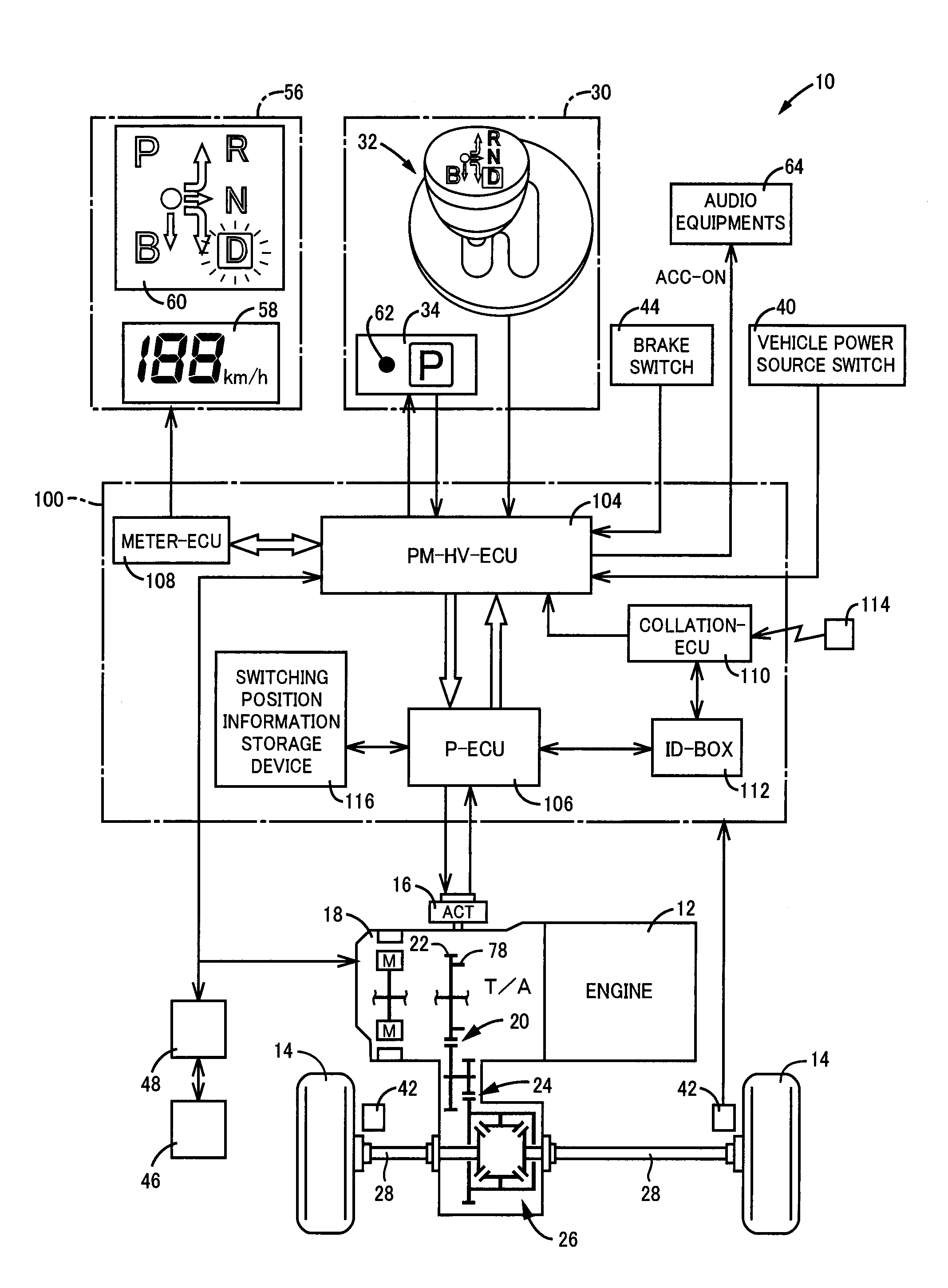
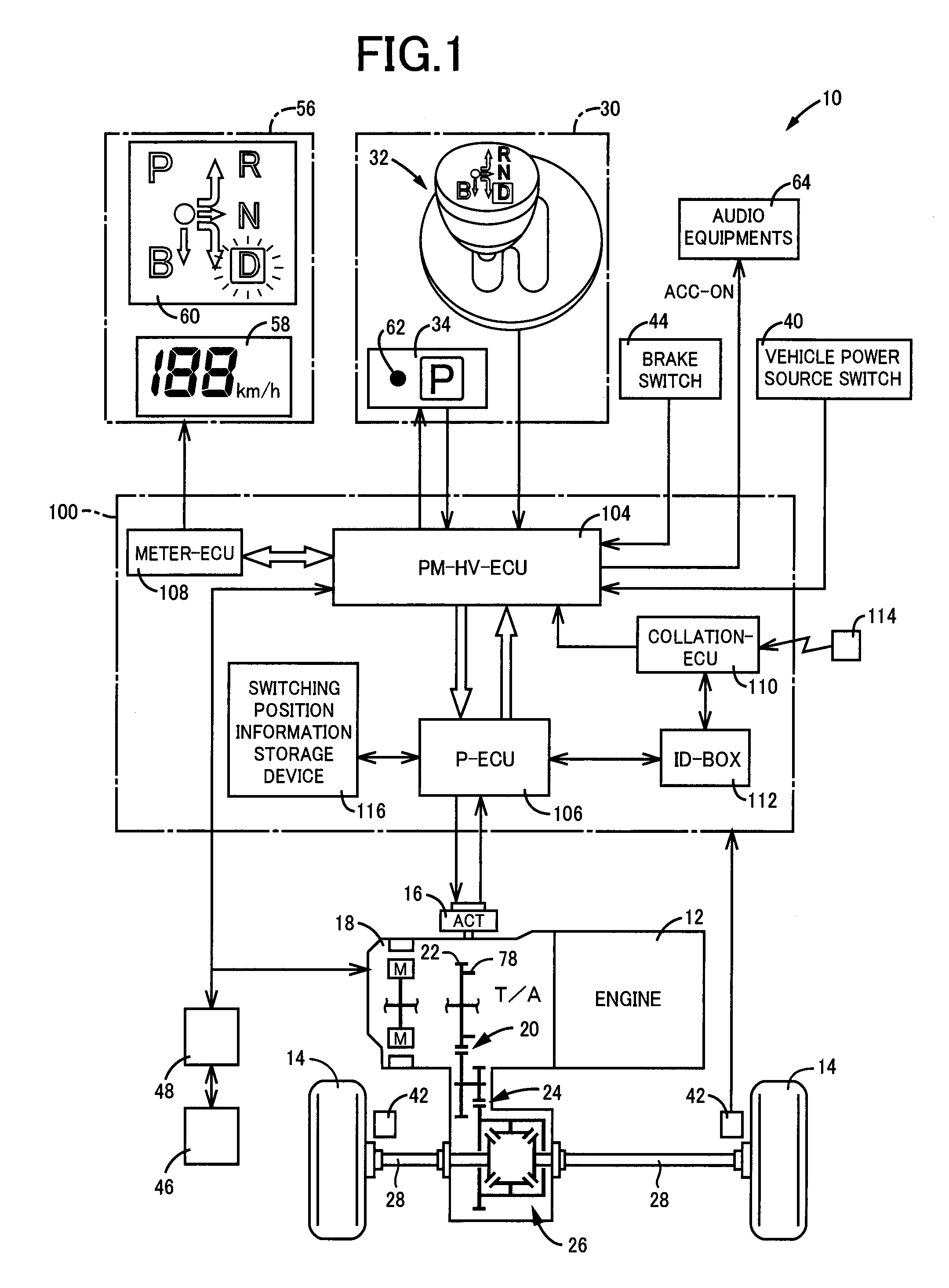
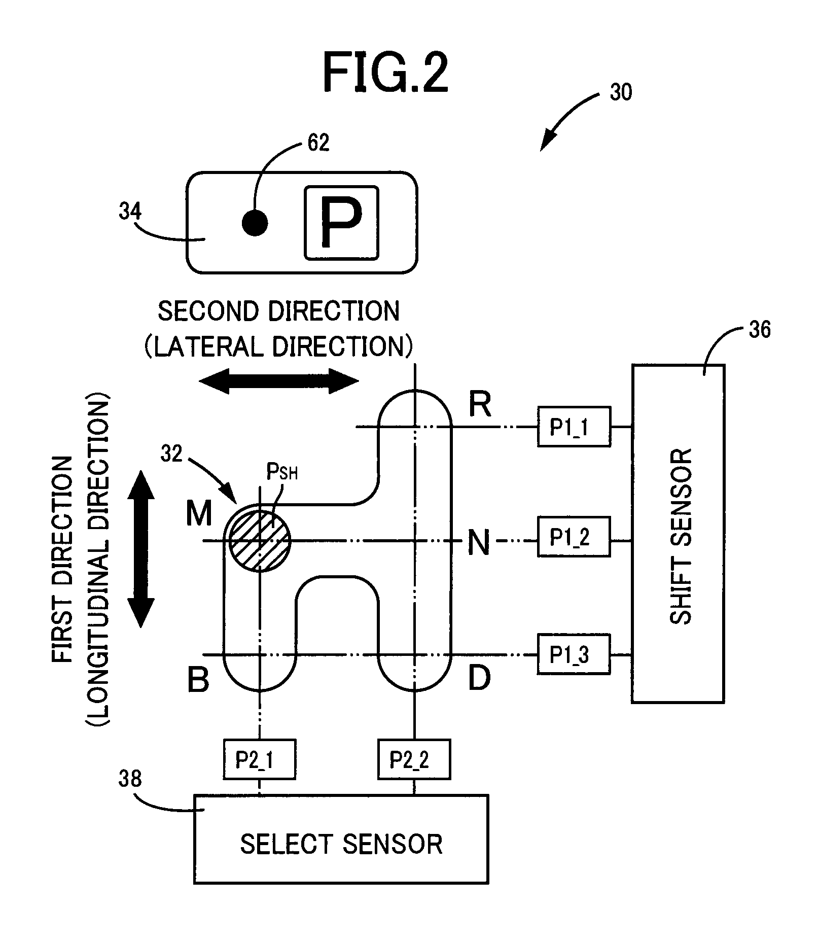
[0032]FIG. 1 is a view for illustrating schematic structure of a power transmitting path between an engine 12 and drive wheels 14 in structure of a vehicle 10 to which the present invention is applied and represents a block diagram for illustrating an essential part of a control system provided on the vehicle 10 for controlling a parking lock device 16 or the like. In FIG. 1, the vehicle 10 includes the parking lock device 16, a transmission 18, and a shift operation device 30, etc. and adopts a shift-by-wire (SBW) system for electrically switching shift positions related to the running of the vehicle 10, i.e., shift positions (shift ranges) of the transmission 18. Further, the transmission 18 is of the type that is preferably applied to, for instance, a FF (Front Engine Front Drive) vehicle to be transversely located in the vehicle 10. This allows power of the engine 12 in the form of an internal combustion engine playing a role as a running drive power source to be transmitted fro...


PUM


Abstract

It is provided a shift control device for a vehicle having a parking lock device driven by an actuator to selectively switch switching positions between a lock position and an unlock position, wherein when a run-enable operation is made by a driver and a non-running state is switched to a running state, shift position recognizing control is executed for recognizing an initial switching position appearing at the beginning when the running state is established, by driving the actuator in response to switching position information indicative of the switching position on a stage before the running state is established, wherein: the non-running state is configured to be switched to the running state prior to the execution of the run-enable operation; and updating of the switching position information, stored in the switching position information storage device, is permitted to be executed subjected to the switching position recognizing control being executed.

Description

CROSS-REFERENCE TO RELATED APPLICATIONS[0001]This application is a continuation-in-part application of International Application No. PCT / JP2009 / 071349, filed Dec. 22, 2009, the content of which is incorporated herein by reference.FIELD OF THE INVENTION[0002]The present invention relates to a shift-by-wire technology for a vehicle having a parking lock device, configured to selectively switch switching positions into a lock position for restricting the rotations of wheels and an unlock position by driving an actuator, wherein, in particular, the shift positions of the vehicle are electrically switched in response to a request signal for switching the switching positions.BACKGROUND ART[0003]A shift control device for a vehicle has been known including a parking lock device for switching rotational teeth, rotatable with wheels, into a lock state for a lock tooth to mesh with the rotational teeth and an unlock state for the lock state to be released. To this end, a so-called shift-by-wi...

Claims


Application Information

Patent Timeline
Patent Type & Authority Patents(United States)
IPC IPC(8): F16H59/74
CPCF16H63/3466F16H59/10F16H63/483
Inventor KITAORI, ICHIROTSUTSUMI, TAKAHIKOKANAI, OSAMUUENO, KOKISEKIYA, KEISUKESUZUKI, TOSHINARI
Owner TOYOTA JIDOSHA KK
Learn More