Drive device for railway vehicle

a technology for driving devices and railway vehicles, which is applied in the direction of motor/generator/converter stoppers, dynamo-electric converter control, propulsion by batteries/cells, etc. it can solve the problems of insufficient braking force, so as to prevent overcharging or overcharging of energy storage devices, suppress the effect of abrupt change in voltage of dc portion, and improve flexibility in selecting energy storage devices

Inactive Publication Date: 2014-08-26
HITACHI LTD
View PDF3 Cites 0 Cited by
  • Summary
  • Abstract
  • Description
  • Claims
  • Application Information

AI Technical Summary

Benefits of technology

[0012]In order to solve the above-described problems, a drive device for a railway vehicle according to the present invention includes a pantograph for receiving DC power from a DC voltage source, an inverter device for converting the DC power into AC power, at least one or more AC motors driven by the inverter device, a chargeable and dischargeable energy storage device, and a voltage adjustment device that adjusts the output voltage thereof by using a current control device disposed between the positive and negative electrodes of the energy storage device and configured to switch the connection to the positive electrode side or the negative electrode side of the energy storage device, and is configured such that the energy storage device is connected in series with the inverter device to make the output voltage of the voltage adjustment device added to the voltage of the DC voltage source, and thereby the voltage applied to the inverter device is increased so as to increase the regeneration braking force. Further, the drive device for the railway vehicle according to the present invention is configured such that, when the power running operation or the regeneration operation of the inverter device is started, the operation of the current control device is started prior to the start of the power running operation or the regeneration operation of the inverter device, and such that, when the power running operation or the regeneration operation of the inverter device is stopped, the operation of the current control device is stopped later than the stopping of the power running operation or the regeneration operation of the inverter device. Thereby, the current control device is surely operated at least during the period of the power running operation or the regeneration operation of the inverter device, so that the output voltage of the voltage adjustment device (current flowing through the energy storage device) is adjusted by the current control device, and thereby it is possible to prevent the over-discharge of the energy storage device at the time of the power running operation or to prevent the overcharge of the energy storage device at the time of the regeneration operation.
[0013]According to the present invention, it is possible to surely avoid the power running operation or the regeneration operation of the inverter device in the state where the operation of the chopper is stopped, and hence it is possible to prevent the over-discharge or overcharge of the energy storage device. Further, since the output voltage of the voltage adjustment device is always controlled by the chopper, the restriction on the voltage between the terminals of the energy storage device is removed, and hence the flexibility of selecting the energy storage device is improved. Further, it is possible to suppress an abrupt change in the voltage of the DC portion of the inverter device at the time when the power running operation or the regeneration operation of the inverter device is started and stopped, and hence it is also possible to prevent an over voltage or over current from being applied to the inverter device.

Problems solved by technology

However, a problem with the regeneration brake control is that sufficient braking force is not obtained because the regeneration performance is limited by the performance of the main motor or an inverter device in the high-speed range (higher than the terminal velocity of constant torque region).
However, in the technique described in Patent Document 1, the start timing of the chopper is not considered, and hence the technique has a problem that, when the inverter device performs the regeneration operation in a state where the chopper is not operated, that is, in the state where the switching element (current control device) of the chopper is turned off, the regeneration current always flows through the energy storage device so as to cause the energy storage device to be overcharged.
Therefore, there is a design limitation that it is necessary to use an energy storage device in which the voltage between the terminals of the energy storage device is not more than a voltage resulting from subtracting the DC power source voltage (overhead line voltage) from the withstand voltage of the inverter device.
Further, there is also a problem that, when the regeneration operation of the inverter device is started and stopped in the state where the switching element of the chopper is turned off, the voltage of the DC portion of the inverter device has a value resulting from instantaneously adding and subtracting the voltage between the terminals of the energy storage device, as it is, to and from the DC power source voltage (overhead line voltage), and hence an over voltage and over current is also applied to the inverter device.

Method used


Image

  • Drive device for railway vehicle
  • Drive device for railway vehicle
  • Drive device for railway vehicle

Examples


embodiment 1

[Embodiment 1]

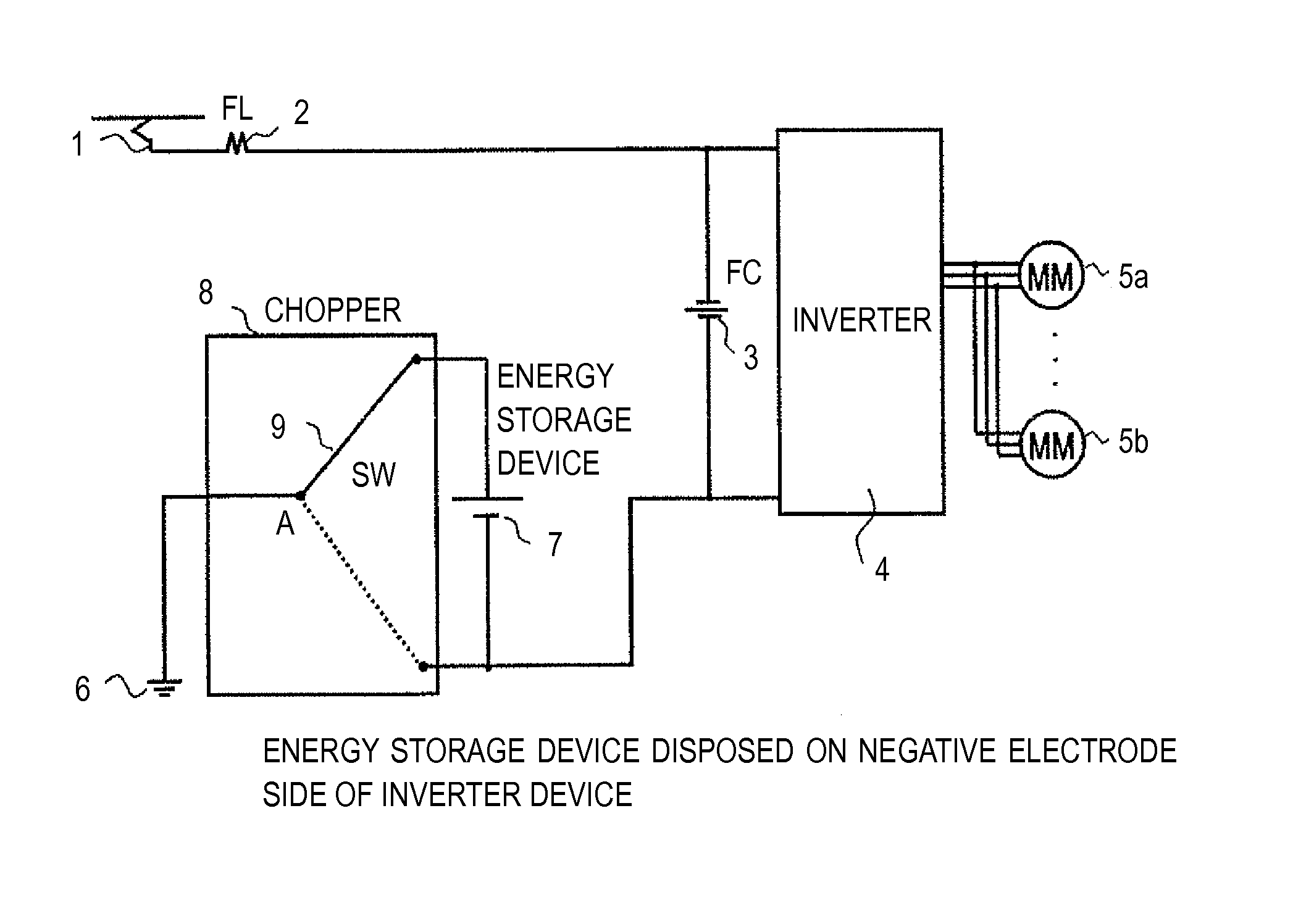
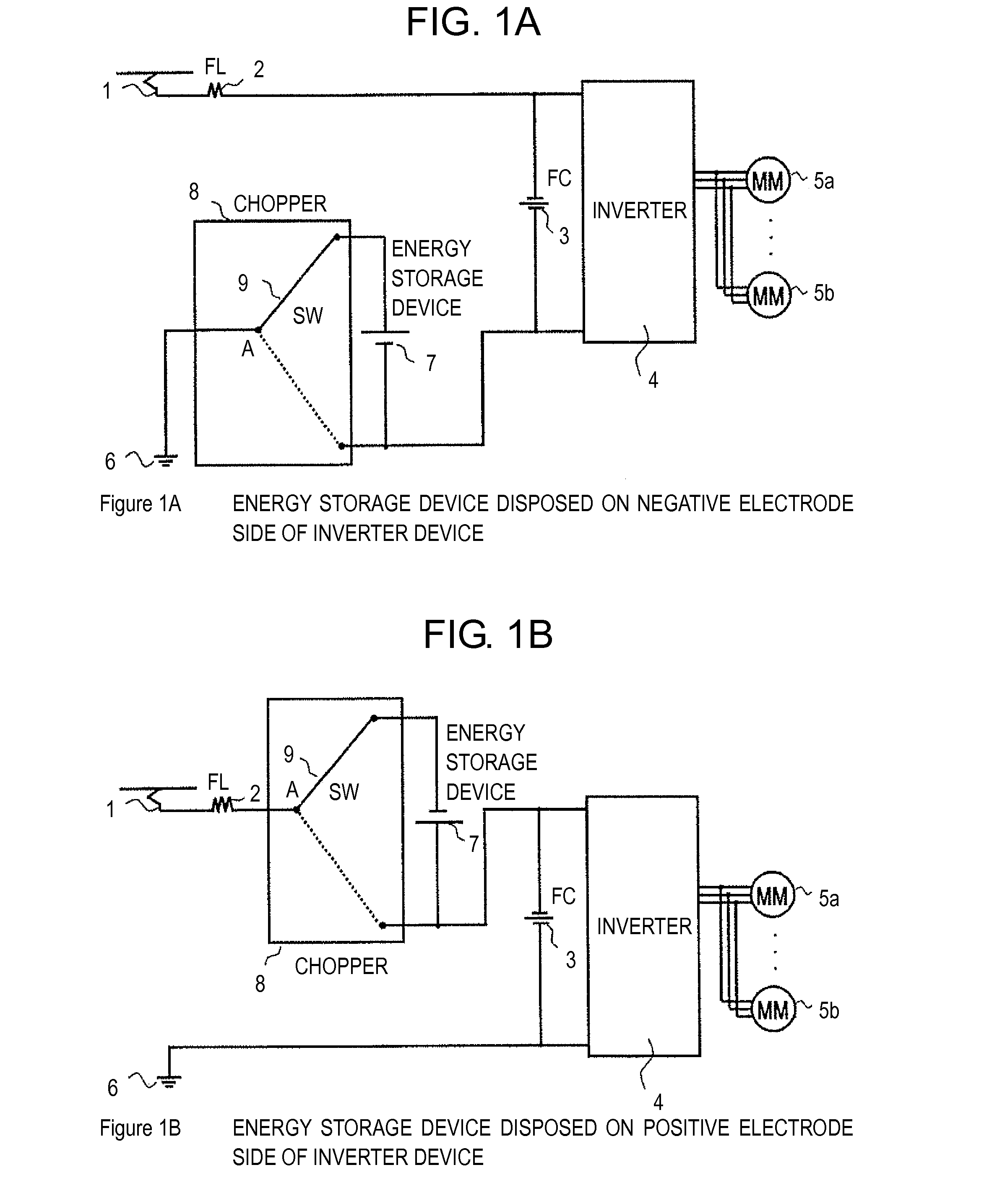
[0035]FIG. 1 shows a basic configuration of a first embodiment of a drive device for a railway vehicle, which is a subject of the present invention. FIG. 3 shows control sequences at the time of power running operation and at the time of regeneration operation in the present embodiment.

[0036]As shown in FIG. 1, a drive device for a railway vehicle, which is a subject of the present invention, includes a pantograph 1 for receiving DC power from a DC voltage source, such as an overhead line, an LC circuit (filter circuit) constituted by a filter reactor (FL) 2 and a filter capacitor (FC) 3 so as to remove high frequency variations in the DC power received by the pantograph 1, an inverter device 4 for converting the DC power into AC power, at least one or more AC motors 5a and 5b driven by the inverter device 4, a chargeable and dischargeable energy storage device 7 (such as, for example, a battery and a capacitor), and a voltage adjustment device that adjusts the output ...

embodiment 2

[Embodiment 2]

[0054]FIG. 5 shows a basic configuration of a second embodiment of a drive device for a railway vehicle, which is a subject of the present invention. FIG. 9 shows a control sequence at the time of regeneration operation in the present embodiment.

[0055]The basic configuration of the second embodiment is different from the basic configuration of the first embodiment shown in FIG. 1 in that the chopper 8 is not constituted by the switch 9, but is constituted by switching elements 10a and 10b which are current cutout devices respectively formed of semiconductor elements, diode elements 11a and 11b each of which is connected in parallel to the input and output terminals of each of the switching elements 10a and 10b in the direction opposite to the direction of conduction of each of the switching elements 10a and 10b, and a smoothing reactor (MSL) 12. Further, the energy storage device 7 and the chopper 8 are disposed between the low potential side terminal of the inverter d...

embodiment 3

[Embodiment 3]

[0075]FIG. 11 shows a basic configuration of a third embodiment of a drive device for a railway vehicle, which is a subject of the present invention. FIG. 15 shows a control sequence at the time of power running operation in the present embodiment.

[0076]The basic configuration of the third embodiment is different from the basic configuration of the second embodiment shown in FIG. 5 in that the energy storage device 7 and the chopper 8 are not disposed between the low potential side terminal of the inverter device 4 and the grounding point 6 of the DC voltage source, but are disposed between the pantograph 1 for receiving DC power from the DC voltage source and the high potential side terminal of the inverter device 4.

[0077]In more detail, as shown in FIG. 11, the third embodiment includes the pantograph 1 for receiving DC power from the DC voltage source, such as an overhead line, the filter capacitor (FC) 3 for removing high frequency variations in the DC power receiv...


PUM


Abstract

In a drive device for a railway vehicle, in which regeneration braking force is increased by adding the output voltage of a voltage adjustment device to a DC power source voltage, operation of the current control device is started prior to the start of the power running operation or the regeneration operation of the inverter device, and the operation of the current control device is stopped later than the stopping of the power running operation or the regeneration operation of the inverter device. Thereby, the current control device is surely operated at least during the operation period of the inverter device, so that the output voltage of the voltage adjustment device is adjusted by the current control device, to thereby prevent the over-discharge of the energy storage device at the time of power running operation or the overcharge of the energy storage device at the time of regeneration operation.

Description

[0001]The present application is based on and claims priority of Japanese patent application No. 2011-200106 filed on Sep. 14, 2011, the entire contents of which are hereby incorporated by reference.BACKGROUND OF THE INVENTION[0002]1. Field of the Invention[0003]The present invention relates to a drive device for a railway vehicle, on which an energy storage device is mounted. More particularly, the present invention relates to a drive device for a railway vehicle, which can realize a function (hereinafter referred to as a high-speed range electric brake function) of extending a speed range for operation of a regeneration brake.[0004]2. Description of the Related Art[0005]In the field of railway vehicles, there has been widely used regeneration brake control in which a main motor is operated as a generator at the time of braking so as to convert the kinetic energy of the vehicle into electrical energy and return the energy to the overhead line while obtaining a braking force. The el...

Claims


Application Information

Patent Timeline
Patent Type & Authority Patents(United States)
IPC IPC(8): H02P3/14
CPCY02T10/648Y02T10/7005B60L11/1801B60L2200/26Y02T10/70B60L50/53B60L7/12H02P3/18Y02T10/64
Inventor ARAKI, DAIJIROSHIMADA, MOTOMIMIYAJI, YOSHIHIROSUZUKI, KEITASUZUKI, KEISHI
Owner HITACHI LTD
Why Eureka
Try Eureka