
Traffic management system

a traffic management system and real-time technology, applied in the direction of controlling traffic signals, digital computers, instruments, etc., can solve the problems of no commercially available products that allow for remote and local monitoring and control of mobile traffic lights, including demand-based sequencing

Active Publication Date: 2014-08-26
SUPERIOR TRAFFIC SYST
View PDF20 Cites 27 Cited by
  • Summary
  • Abstract
  • Description
  • Claims
  • Application Information

AI Technical Summary

Benefits of technology

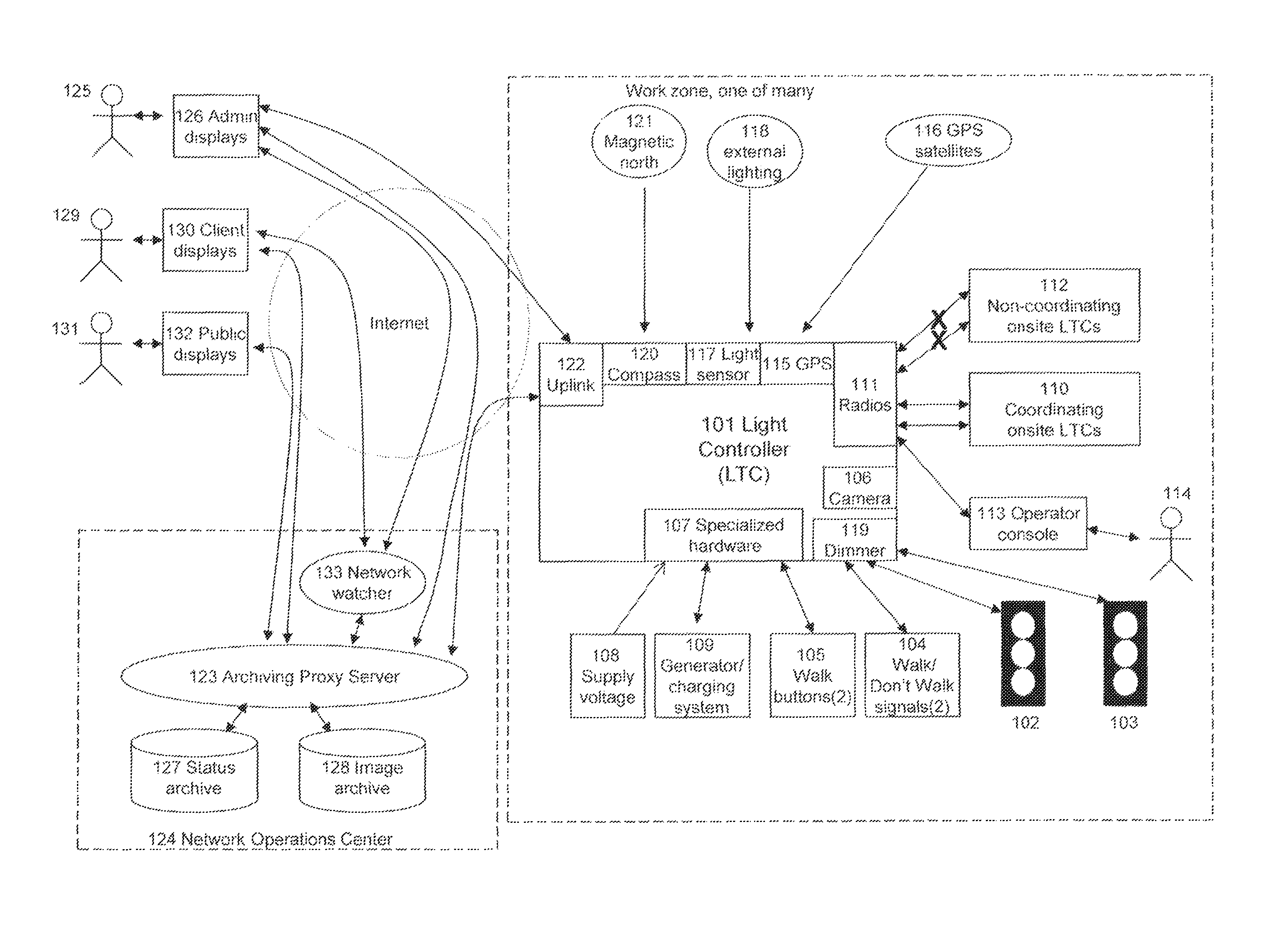
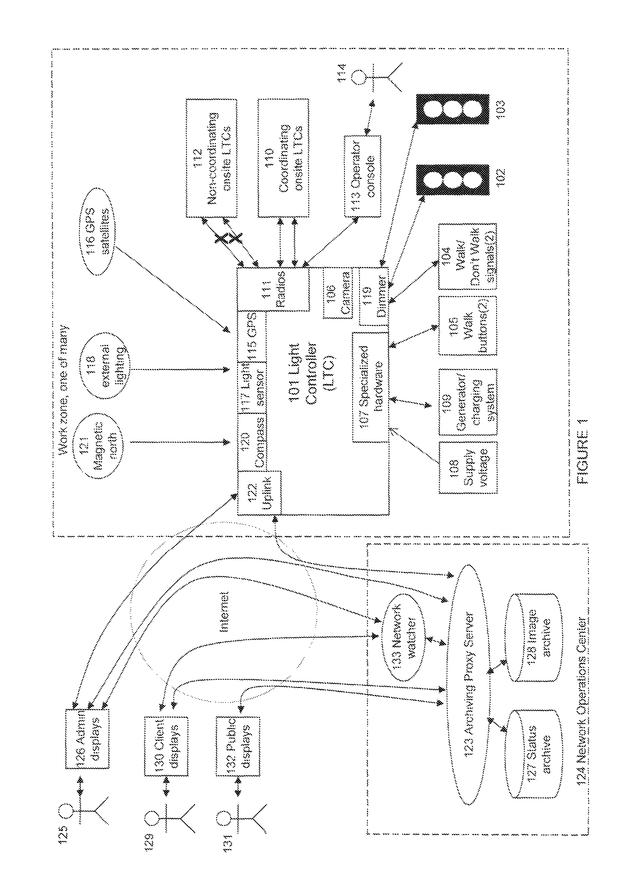
The present invention is a real-time traffic management system that includes a main light controller module, a master control unit server software application, a network operations control module, and a network watcher application program. The main light controller module uses a camera to detect vehicle demand and provides live images for situational awareness. The main light controller module is in communication with one or more coordinating light controller modules, onsite personnel, and a network operations center. The network watcher application program continuously scans incoming data, monitors system performance, and alerts personnel of events or conditions outside of established tolerances. The main light controller module receives commands from and reports status to an archiving proxy server that actively requests status and images for immediate and long-term retrieval. The main light controller module uses timing information derived from a global positioning satellite signal to synchronize flasher mode phase transitions to an atomic clock, thereby synchronizing flasher mode phase transitions of all traffic signals controlled by the main light controller module. The main light controller module has a standard operating mode, a flasher operating mode, and a pilot car operating mode. The technical effects of the present invention include improved traffic management and situational awareness through live monitoring and control of traffic lights, as well as secure monitor and control access to intersections from any location and improved synchronization of flasher mode phase transitions of all traffic signals.

Problems solved by technology

At present, there are no commercially available products that allow for the remote and local monitoring and control of groups of mobile traffic lights, including demand-based sequencing.

Method used


Image

  • Traffic management system
  • Traffic management system
  • Traffic management system

Examples


Embodiment Construction

[0038]A. Overview

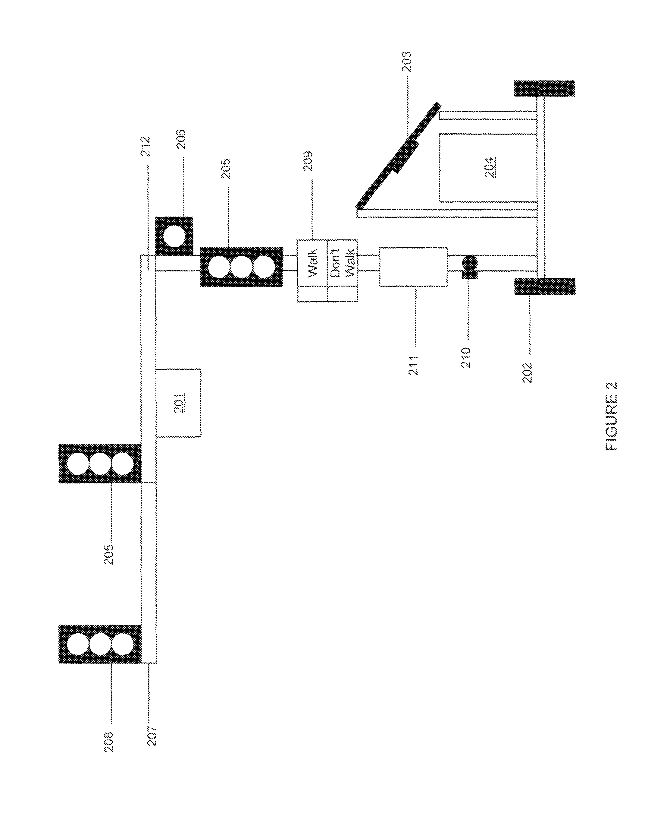
[0039]The present invention is a real-time traffic management system for portable or temporary traffic signals that allows the user to program and monitor groups of portable traffic signal systems in real time over the Internet. Once the light controller (LTC) module is installed on a portable traffic signal, the network operations control (NOC) module, which is at a fixed geographic location, is able to establish communications with the control module, verify that all equipment is working properly, and program the system to control traffic according to the desired program. Through the use of live video feeds of the traffic approaching each signal, the control center is able to establish vehicle demand detection locations for each lane that the signals are controlling and utilize these vehicle arrival events as part of the program. The live video also allows our control center to monitor the traffic approaching each signal to verify that the program is efficiently h...


PUM


Abstract

A real-time traffic management system comprising a main light controller module configured to monitor and control functionality of one or more traffic lights, a master control unit server software application, a network operations control module, and a network watcher application program. The main light controller module communicates with one or more coordinating light controller modules, onsite personnel, and a network operations center. The main light controller uses a camera that detects instances of vehicle demand and provides live images for situational awareness. The main light controller module comprises a global positioning satellite receiver and a light sensor for monitoring ambient lighting conditions. The network watcher application program continuously scans incoming data, monitors performance of all components in the system, and issues alerts and alarms to notify personnel of events or conditions outside of established tolerances.

Description

BACKGROUND OF THE INVENTION[0001]1. Field of the Invention[0002]The present invention relates generally to the field of traffic management systems, and more specifically, to a real-time traffic management system for portable or temporary traffic signals that allows the user to program and monitor groups of portable traffic signal systems in real time over the Internet.[0003]2. Description of the Related Art[0004]At present, there are no commercially available products that allow for the remote and local monitoring and control of groups of mobile traffic lights, including demand-based sequencing. Examples of prior art traffic management systems include: U.S. Pat. No. 3,729,706 (Hein, 1973); U.S. Pat. No. 4,857,921 (McBride et al., 1989); U.S. Pat. No. 6,064,318 (Kirchner, III et al., 2000); U.S. Pat. No. 7,333,029 (Hammett, 2008): U.S. Pat. No. 7,633,408 (Yingst et al., 2009); U.S. Pat. No. 7,973,676 (Meshkin et al. 2011); and U.S. Pat. No. 8,319,662 (Bontemps et al. 2012). None of t...

Claims


Application Information

Patent Timeline
IPC IPC(8): G08G1/0955G08G1/081G06F13/12G06F13/38G08G1/097G06F13/00
CPCG08G1/097G08G1/0955G08G1/081G08G1/04G08G1/08
Inventor WALTHER, JONATHAN Y.HOLLENBACK, JEFFERY M.
Owner SUPERIOR TRAFFIC SYST
Learn More