Device for a motor vehicle comprising a movably mounted camera unit and motor vehicle

a camera unit and motor vehicle technology, applied in the direction of vehicle components, camera body details, instruments, etc., can solve the problems of inconvenient failure of the camera on the protective element, the camera unit attached to the protective element is exposed to a certain degree of dirt and moisture, and the camera can be easily damaged, so as to achieve a simple and cost-effective manner.

Inactive Publication Date: 2014-09-02
HUF HULSBECK & FURST GMBH & CO KG
View PDF16 Cites 19 Cited by
  • Summary
  • Abstract
  • Description
  • Claims
  • Application Information

AI Technical Summary

Benefits of technology

[0009]Such a device for a motor vehicle, having a movably mounted camera unit, is designed in a simple and cost-effective manner, and ensures secure protection of the camera unit from external influences, particularly impacts or percussion, particularly when the protective element is in the closed position.
[0027]The pivot arm of the device can be designed in various different ways. The pivot arm is preferably designed with an angled profile. In this case, the pivot arm can be designed as a single piece or as having multiple pieces, particularly two pieces. In the case of a multi-part construction of the pivot arm, the different parts of the pivot arm are rigidly connected to each other during operation of the device. In the case of a two- or multi-part design of the pivot arm, it is advantageous that individual parts can be exchanged in a simpler and more cost-effective manner than in the case of a pivot arm designed as a single piece. The pivot arm and / or the individual parts of the pivot arm are preferably constructed of plastic or metal, and particularly of light metal. A pivot arm designed as a single piece has a hole, particularly in the center and / or in the region of the center of the pivot arm, through which the pivot arm is rotatably mounted on the second axis of the device. If the pivot arm is designed as two pieces, for example, the two parts and / or two limbs of the pivot arm each have a hole which serves the purpose of mounting the two parts on the second axis.

Problems solved by technology

The indirect arrangement of the camera on the protective element has proven to be disadvantageously prone to failure.
Due to the effects of weather and to the appearance of wear, after a certain period of time the protective element no longer provides an acceptable seal, such that the camera unit attached on the protective element is exposed to a certain degree of dirt and moisture.
In addition, the camera can be easily damaged by impacts or percussion to the protective element due to its direct arrangement on the protective element.
A disadvantage of this device is that the motor has a first mechanism for the purpose of moving the camera unit, and a second mechanism for the purpose of moving the protective element.
This makes the device complicated from a structural engineering perspective, meaning that the device requires a relatively high number of components, and the manufacture of the device is therefore also cost-intensive.

Method used


Image

  • Device for a motor vehicle comprising a movably mounted camera unit and motor vehicle
  • Device for a motor vehicle comprising a movably mounted camera unit and motor vehicle
  • Device for a motor vehicle comprising a movably mounted camera unit and motor vehicle

Examples


Embodiment Construction

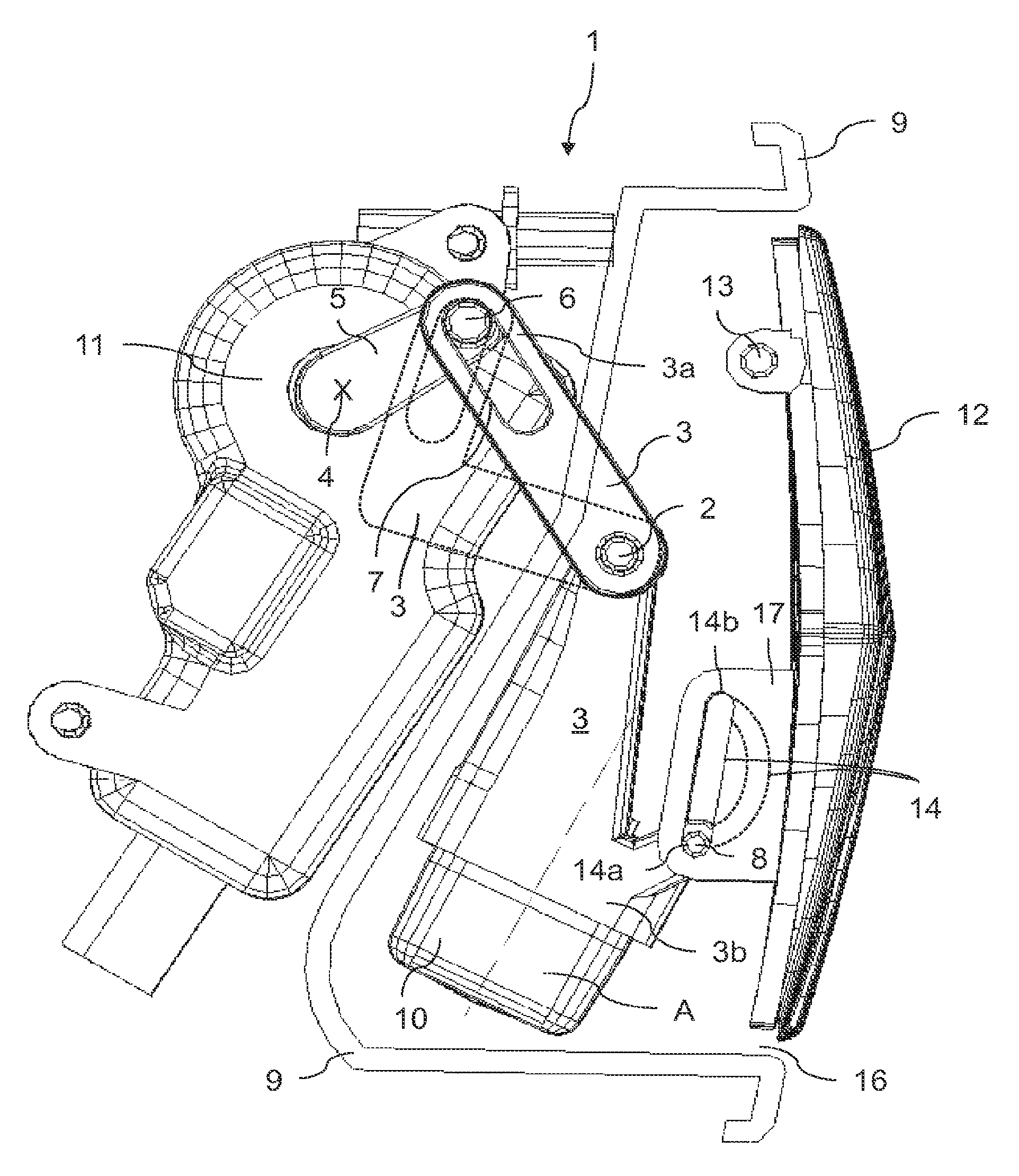
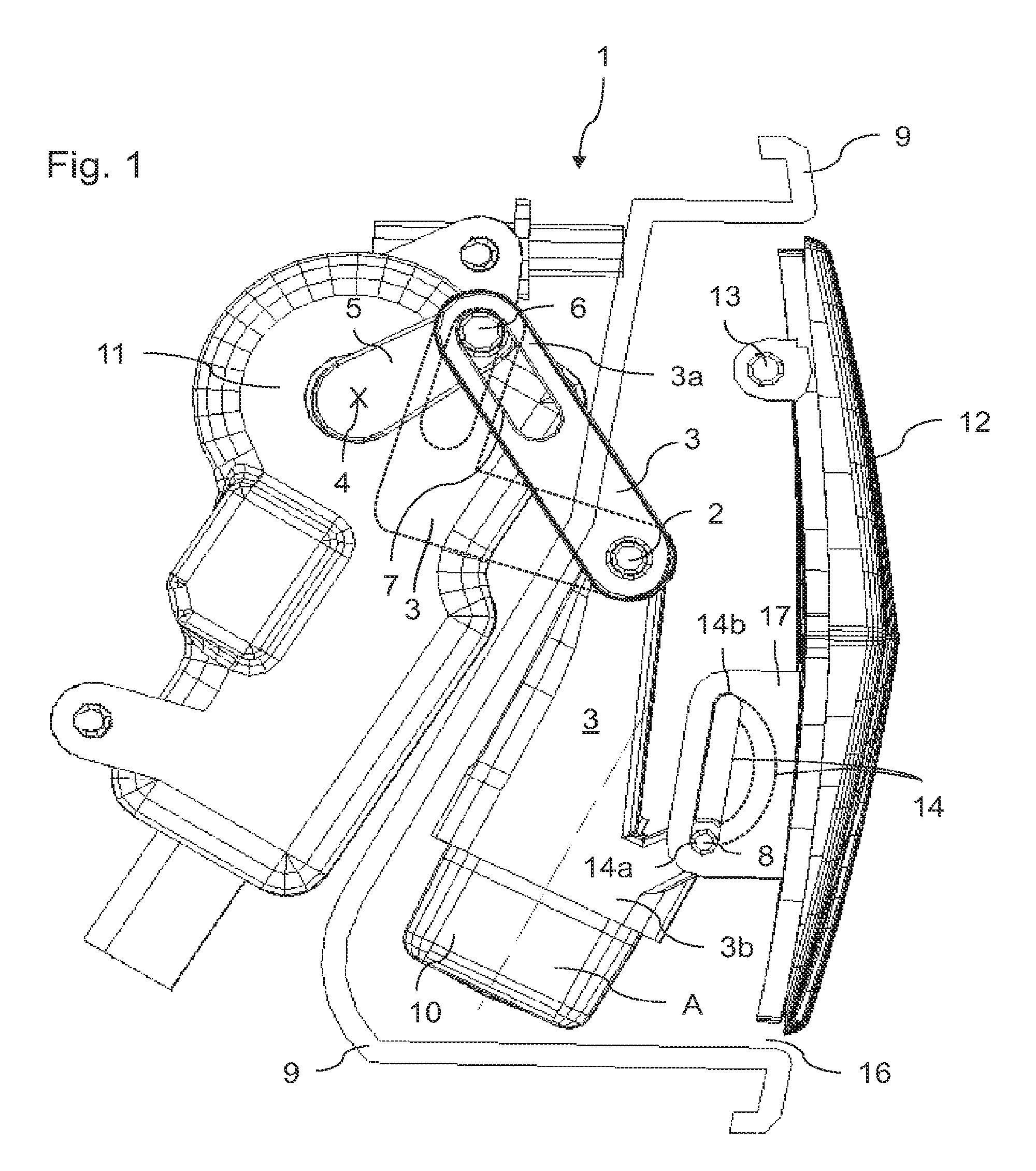
[0036]Elements which have the same function and mode of action are indicated by the same reference numbers in FIGS. 1 to 3.

[0037]FIG. 1 shows a side view of one embodiment variant of the device 1 for a motor vehicle, having a movably mounted camera unit 10 which is designed according to the constructive principle according to the invention, wherein the camera unit 10 is in the standby position A and the protective element 12 is in the closed position. The device 1 has a drive unit 11 which has a functional connection to a pivot arm 3 of the device 1. The pivot arm 3 connects the drive unit 11 to the protective element 12. In this embodiment variant of the device 1, the pivot arm 3 is designed having two parts, and both parts of the pivot arm 3 are rigidly connected to each other. The pivot arm 3 is designed with an angled profile and is rotatably mounted about a second axis 2 of the device 1. The end of the pivot arm 3 which is closest to the drive unit 11, the so-called first end 3...


PUM


Abstract

The invention relates to a device (1) for a motor vehicle, comprising a movably mounted camera unit (10), which can be brought into an idle position (A) and an active position (B) by means of a drive unit (11), and to a protection element (12), which can be transferred into a closed position and an open position, wherein the camera unit (10) is located in the idle position thereof inaccessible from the outside behind the protection element (12) when the protection element (12) is in the closed position and the camera unit (10) is located in the active position for image acquisition when the protection element (12) is in the open position wherein the camera unit (10) is arranged on a movably mounted pivot arm (3), which connects the drive unit (11) to the protection element (12), wherein a movement of the pivot arm (3) triggered by the drive unit (11) can transfer the protection element (12) into the closed position and open position and the camera unit (10) into the idle position and the active position. The invention further relates to a vehicle, in particular a motor vehicle, comprising such a device.

Description

TECHNICAL FIELD[0001]The invention relates to a device for a motor vehicle, having a movably mounted camera unit which can be brought into a standby position and into an active position via a drive unit, and having a protective element which can be guided into a closed position and an open position, wherein the camera unit is in its standby position and is not accessible from outside behind the protective element when the same is in the closed position, and the camera unit is in the active position to capture an image when the protective element is in the open position. The invention also relates to a motor vehicle having a rotatably mounted camera unit.BRIEF SUMMARY OF RELATED ART[0002]The use of cameras and / or of a camera unit for the purpose of detecting the environment of a vehicle is known. Such camera units are used, for example, as parking and / or maneuvering aids, particularly to image the areas around the automobile which cannot be seen with the conventional mirrors of the m...

Claims


Application Information

Patent Timeline
Patent Type & Authority Patents(United States)
IPC IPC(8): G03B17/00
CPCB60R11/04B60R2011/0082
Inventor SCHUTZ, HEIKO
Owner HUF HULSBECK & FURST GMBH & CO KG
Why Eureka
Try Eureka