Clamp mechanism for clamping a cable

a technology of clamping mechanism and cable, which is applied in the direction of fixed connection, coupling device details, coupling device connection, etc., can solve the problems of low product manufacturing yield, complicated structure of conventional cable clamping mechanism, and long assembly period, etc., to achieve fast assembly and disassembly, and simple structure

Active Publication Date: 2014-09-02
WISTRON CORP
View PDF19 Cites 2 Cited by
  • Summary
  • Abstract
  • Description
  • Claims
  • Application Information

AI Technical Summary

Benefits of technology

[0016]The clamp mechanism of the present invention has simple structure, and can be assembled and disassembled rapidly without structural destruction. In addition, the clamp mechanism of the present invention has advantages of low cost and easy operation, so as to effectively increase the manufacturing yield of the product, and to speed the manufacturing period for enhancing market competition.

Problems solved by technology

The conventional cable clamp mechanism has drawbacks of complicated structure, expensive manufacturing cost and long assembly period.
The pressing portion of the conventional cable clamp mechanism is movably disposed on the base, so the pressing portion is abraded easily by external force that results in low manufacturing yield of the product.
Thus, design of a cable clamp mechanism having simple structure, low manufacturing cost and easy operation is an important issue in the mechanical industry.

Method used


Image

  • Clamp mechanism for clamping a cable
  • Clamp mechanism for clamping a cable
  • Clamp mechanism for clamping a cable

Examples


Embodiment Construction

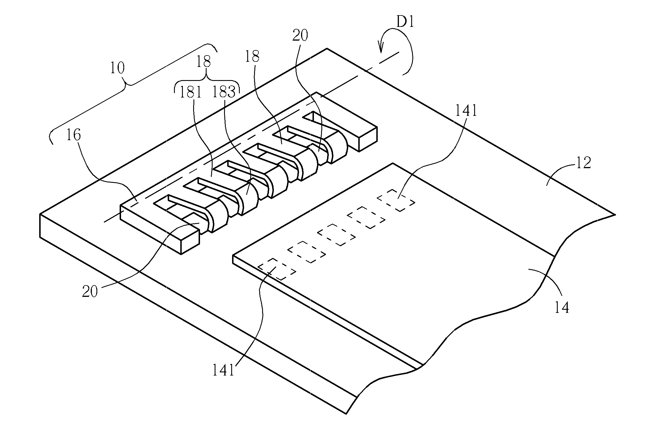
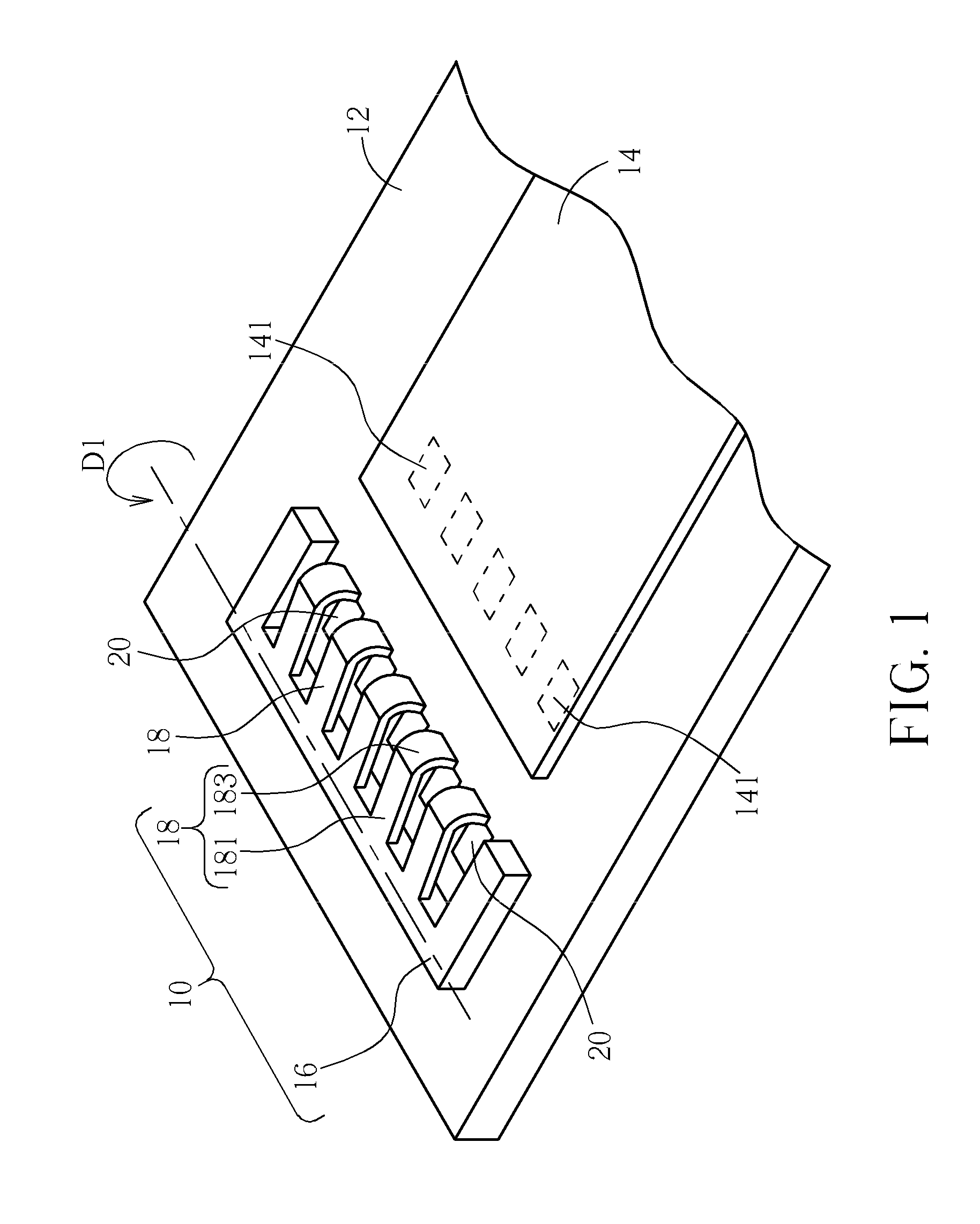
[0023]Please refer to FIG. 1, a diagram of a clamp mechanism 10 according to a first embodiment of the present invention. The clamp mechanism 10 can be disposed on a circuit board 12 for fixing a cable 14, so as to constrain a movement of the cable 14 relative to the circuit board 12. Generally, the cable 14 can be a flex flat cable (FFC) or a flexible circuit (FPC). The clamp mechanism 10 of the present invention can press on a surface of the cable 14 to steady the cable 14 on the circuit board 12.

[0024]The clamp mechanism 10 can include a base 16 and a plurality of clamping portions 18. The base 16 is disposed on the circuit board 12. The cable 14 can slide relative to the circuit board 12 and be partly accommodated inside the base 16. For example, the base 16 can be a U-shaped structure. An inner space of the U-shaped structure surrounds an end of the cable 14. The plurality of clamping portions 18 is separately disposed on an edge of the base 16 adjacent to the inner of the U-sh...


PUM


Abstract

A clamp mechanism for clamping a cable on a circuit board is disclosed in the present invention. The clamp mechanism includes a base disposed on the circuit board. The cable can be accommodated inside the base. The clamp mechanism further includes a clamping portion disposed on the base in a resiliently deformable manner. The clamping portion moves away from the circuit board when the cable is accommodated inside the base, and a resilient recovering force generated by the resilient deformation simultaneously drives the clamping portion to press the cable, so as to constrain a movement of the cable relative to the base.

Description

BACKGROUND OF THE INVENTION[0001]1. Field of the Invention[0002]The present invention relates to a clamp mechanism, and more particularly, to a clamp mechanism for fixing a cable on a circuit board.[0003]2. Description of the Prior Art[0004]A conventional cable clamp mechanism includes a base and a pressing portion, the pressing portion is disposed on the base in a pivotable manner. As assembling the cable, the pressing portion is manually driven to pivot relative to the base at an open position, so as to enlarge an opening of the base. Then the cable is inserted into the base through the opening, and the pressing portion is rotated from the open position to a close position, so as to press a surface of the cable for preventing the cable from separating from the base. The conventional cable clamp mechanism has drawbacks of complicated structure, expensive manufacturing cost and long assembly period. The pressing portion of the conventional cable clamp mechanism is movably disposed o...

Claims


Application Information

Patent Timeline
Patent Type & Authority Patents(United States)
IPC IPC(8): H01R4/50H01R13/625
CPCH01R12/62H01R12/65
Inventor YANG, CHUN-FEI
Owner WISTRON CORP
Why Eureka
Try Eureka