Supercharge Your Innovation With Domain-Expert AI Agents!

Method for preparing samples for imaging

a technology of electron microscopy and sample preparation, applied in the direction of material analysis using wave/particle radiation, instruments, etc., can solve the problems of lamella bending, over-milling, and other catastrophic defects, so as to reduce or prevent bending and curtaining, reduce or eliminate curtaining, and reinforce the structural integrity of the sample

Active Publication Date: 2014-09-02
FEI CO
View PDF6 Cites 11 Cited by
  • Summary
  • Abstract
  • Description
  • Claims
  • Application Information

AI Technical Summary

Benefits of technology

[0025]In embodiments for producing a TEM sample, TEM lamellae less than 60 nanometers thick, more preferably 30 nm or less in thickness, are produced in a manner that reduces or prevents bending and curtaining. Some embodiments deposit material onto the face of a TEM sample during the process of preparing the sample. In some embodiments, the material can be deposited on a sample face that has already been thinned before the opposite face is thinned, which can serve to reinforce the structural integrity of the sample and refill areas that have been over-thinned due to the curtaining phenomena.
[0026]In some embodiments, such as when milling a cross section having layers of materials having different hardnesses, a cross section is exposed by ion beam milling and then material is deposited onto the cross section face before a final milling of the cross section face, which deposition can serve to reduce or eliminate curtaining on the sample face. In some embodiments, a deposition gas is provided while the ion beam is milling the cross section, and in some embodiments, the deposition gas is provided during a deposit step before the final milling of the cross section.
[0027]It is noted that dissociation of the precursor can be achieved by exposing the sample (work piece) to energetic electrons, energetic ions, X-rays, light, heat, microwave radiation, or energizing the precursor in any other way, as a result of which the precursor material dissociates in a non-volatile part that forms the deposit and a volatile part. Using other energizing means than ion beams, for example using light produced by a laser, might offer advantages when filling irregularities or voids prior to milling. Preferably the precursor is a good electric conductor, for example showing a conductivity of better than 100 μΩ·cm. When depositing occurs simultaneous with milling it makes more sense to use the energetic ion beam to form a deposit.

Problems solved by technology

As features continue to get smaller and smaller, however, there comes a point where the features to be measured are too small for the resolution provided by an ordinary SEM.
Currently thinning below 60 nm is difficult and not robust.
Thickness variations in the sample result in lamella bending, over-milling, or other catastrophic defects.
Unfortunately, ultra thin lamellae formed using the prior art methods described above are subject to undesirable side effects known as “bending” and “curtaining.” When attempting to produce ultra thin samples (for example, 30 nm thickness or less) the sample may lose structural integrity and deform under forces acting on the sample, typically by bending or bowing toward one sample face or the other.
If this occurs during or prior to a FIB thinning step, then the deformation of the region of interest toward or away from the beam may cause unacceptable damage to the sample.
Curtaining artifacts reduce the quality of the TEM imaging and limit the minimal useful specimen thickness.
For ultra-thin TEM samples, the two cross-section faces are in very close proximity so thickness variations from curtaining effects can cause a sample lamella to be unusable.
Curtaining and other artifact are also problems on cross section faces milled by a FIB for viewing with an SEM.
The terracing can cause curtaining artifacts and other artifacts to be formed below the terracing.
The hard aluminum oxide layer shows terracing artifacts, which are difficult to observe in the black region in FIG. 9.
Terraced artifacts can be difficult and time-consuming to prevent using prior art methods for reducing artifacts.
Terracing tends to create severe artifacts, such as severe curtaining, in the region below the terracing.
The most effective and widely proven alternative, backside milling, works reasonably well for TEM samples having a thickness of 50 to 100 nm, but for ultra-thin samples having a sample thickness of 30 nm or less, even samples prepared by backside milling often show milling artifacts resulting in an undesirably non-uniform sample face.
Further, even for thicker samples, backside milling requires a liftout and inversion operation that is very time consuming.
Current backside milling techniques are also performed manually, and are unsuitable for automation.

Method used


Image

  • Method for preparing samples for imaging
  • Method for preparing samples for imaging
  • Method for preparing samples for imaging

Examples


Embodiment Construction

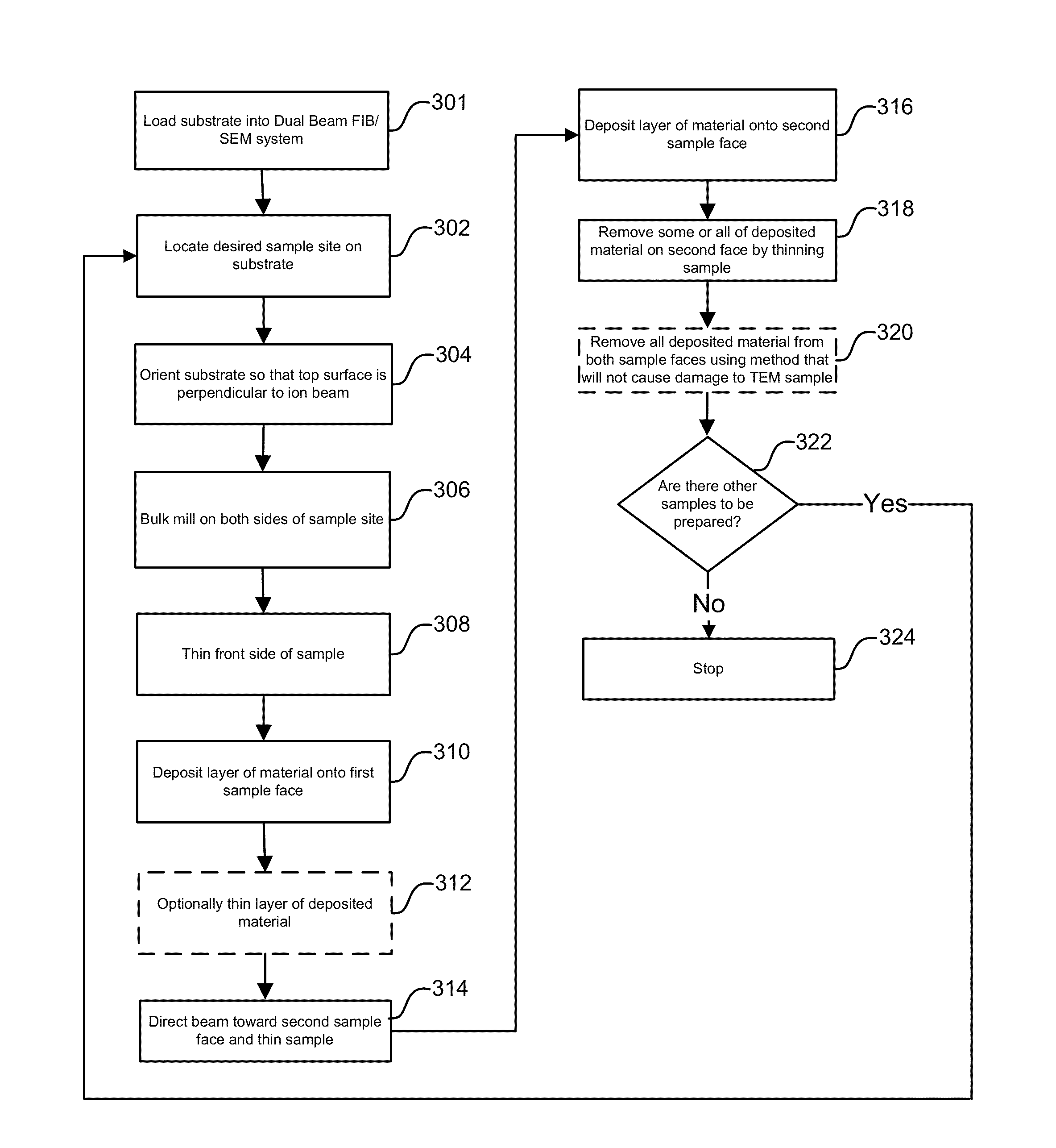
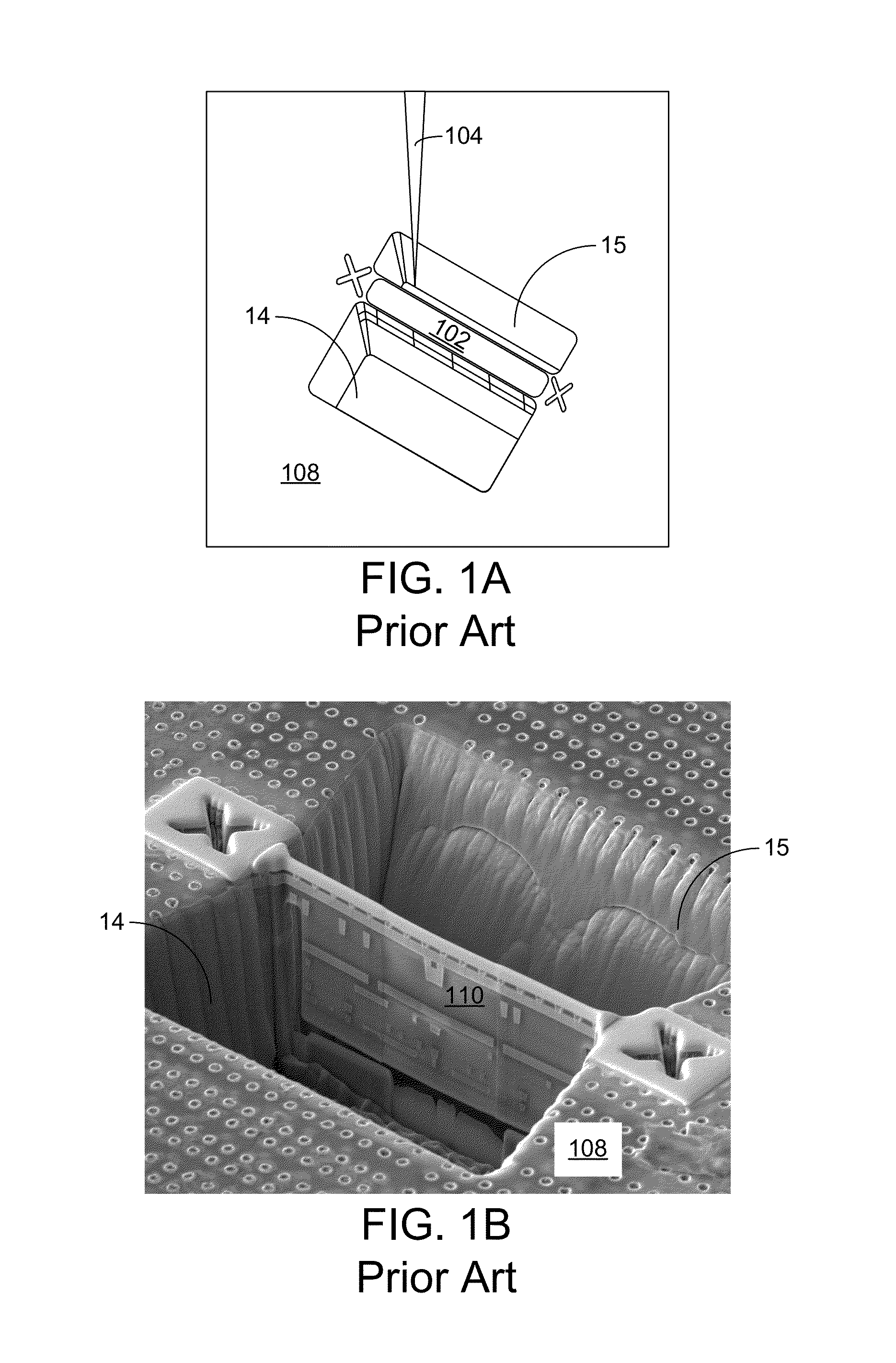
[0046]FIG. 10 is a flowchart showing the steps of an embodiment of the invention. FIGS. 11A-11D shows the sample at different stages of processing. FIG. 11A shows the sample 1102 includes a layer of aluminum oxide 1104 above a layer of aluminum 1106. In step 1002, a region of interest on the sample is identified. In step 1004, a protective layer 1110 is deposited onto the surface of the sample 1104 over the region of interest. The protective layer can be deposited, for example, using ion beam-induced deposition, electron beam-induced deposition, or other local deposition process. Deposition precursors are well known and can include for example, metalloorganic compounds, such as tungsten hexacarbonyl and methylcyclopentadienlylplatinum (IV) trimethyl for depositing metals, or hexamethylcyclohexasiloxane for depositing an insulator.

[0047]In step 1006, a trench 1112 is milled in the sample to expose a cross section 1114 as shown in FIG. 11A. The ion beam 1116 is typically oriented norm...


PUM

PropertyMeasurementUnit
beam currentaaaaaaaaaa
thickaaaaaaaaaa
thicknessaaaaaaaaaa

Abstract

A method and apparatus is provided for preparing samples for observation in a charged particle beam system in a manner that reduces or prevents artifacts. Material is deposited onto the sample using charged particle beam deposition just before or during the final milling, which results in an artifact-free surface. Embodiments are useful for preparing cross sections for SEM observation of samples having layers of materials of different hardnesses. Embodiments are useful for preparation of thin TEM samples.

Description

[0001]This application is a continuation-in-part of U.S. patent application Ser. No. 14 / 081,947, filed Nov. 15, 2013, which claims priority from U.S. Prov. Pat. App. 61 / 747,512, filed Dec. 31, 2012, and is a continuation-in-part of U.S. patent application Ser. No. 13 / 481,351, filed May 25, 2012, which claims priority from U.S. Prov. App. No. 61 / 493,308, filed Jun. 3, 2011, all of which are hereby incorporated by reference.TECHNICAL FIELD OF THE INVENTION[0002]The present invention relates to preparation of samples for electron microscopy and, in particular, to preparation of high quality samples of semiconductors and other materials.BACKGROUND OF THE INVENTION[0003]Semiconductor manufacturing, such as the fabrication of integrated circuits, typically entails the use of photolithography. A semiconductor substrate on which circuits are being formed, usually a silicon wafer, is coated with a material, such as a photoresist, that changes solubility when exposed to radiation. A lithograp...

Claims


Application Information

Patent Timeline
Patent Type & Authority Patents(United States)
IPC IPC(8): G01N23/00G01N1/32
CPCG01N1/32H01J37/3056H01J2237/31745B05D3/044G01N2001/2886G01N1/286H01L21/02318
Inventor SCHMIDT, MICHAELBLACKWOOD, JEFFREYSTONE, STACEYLEE, SANG HOONKELLEY, RONALD
Owner FEI CO
Features
  • R&D
  • Intellectual Property
  • Life Sciences
  • Materials
  • Tech Scout
  • Unparalleled Data Quality
  • Higher Quality Content
  • 60% Fewer Hallucinations
Learn More