Two-portion shallow-trench isolation

a shallow trench and two-portion technology, applied in the direction of basic electric elements, electrical equipment, semiconductor devices, etc., can solve the problems of increasing the aspect ratio of gaps, increasing the difficulty of filling gaps without leaving voids, etc., and achieve excellent gap-filling ability and increase the aspect ratio

Active Publication Date: 2014-09-02
UNITED MICROELECTRONICS CORP
View PDF11 Cites 13 Cited by
  • Summary
  • Abstract
  • Description
  • Claims
  • Application Information

AI Technical Summary

Benefits of technology

[0006]To manufacture shallow trench isolation (STI) structures with increased aspect ratios, a novel shallow trench isolation structure and a method of forming the same are provided in the present invention. A Flowable Chemical Vapor Deposition (FCVD) process is used in the method of present invention to achieve excellent gap-filling ability, and a shallow trench isolation structure with discontinuous upper and lower insulating portions is manufactured through the method of forming a buffer layer in the trench before the FCVD process.

Problems solved by technology

One of the persistent challenges faced in the development of semiconductor technology is the desire to increase the density of circuit elements and interconnections on substrates without introducing unwanted interactions between them.
As circuit densities increase, however, the widths of these gaps or trenches decrease, thereby increasing their aspect ratios and making the gaps progressively more difficult to be filled without leaving voids.
The formation of voids when the gap is not filled completely is undesirable because they may adversely affect the operation of the completed device, such as by trapping impurities within the insulating material.

Method used


Image

  • Two-portion shallow-trench isolation
  • Two-portion shallow-trench isolation
  • Two-portion shallow-trench isolation

Examples


second embodiment

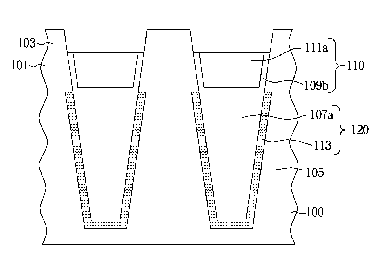
[0030]Please refer to FIGS. 8-10 which are cross-sectional views illustrating the process flow of manufacturing a shallow trench isolation structure in accordance with present invention. In this embodiment, the steam annealing process may be performed before the deposition of second insulating layer 111. As shown in FIG. 8, the steam annealing process is performed after the formation of buffer layer 109, so that the substrate 100 surrounding the first insulator 107a is oxidized and transformed into an insulating layer 113, and the buffer layer 109 is transformed into an oxide layer 109a. Subsequently, as shown in FIG. 9, a second insulating layer 115 is deposited on the oxide layer 109a and in the recess. This process is similar to the step shown in FIG. 6. The difference between the present embodiment and previous embodiment is that, in present embodiment, since the steam annealing is performed before the deposition of the second insulating layer 115, the second insulating layer 11...

third embodiment

[0032]Please refer now to FIG. 11-12 which are cross-sectional views illustrating the process flow for manufacturing a shallow trench isolation structure in accordance with the present invention. In this embodiment, the buffer layer 109 functions as a pure blocking layer which is not oxidized by the steam annealing process. The material of buffer layer 109 may be selected from silicon nitride (SiN) or silicon carbonitride (SiCN). After the buffer layer 109 is formed, as shown in FIG. 11, a selective etching process is first performed to remove a part of the buffer layer 109 on the top surface of the first insulator 107a, thereby forming a spacer 109c structure on the mask layer 103 and the substrate 100. Subsequently, as shown in FIG. 12, the same FCVD process is performed to fill a second insulating layer 111 in the recess 105a. The material of second insulating layer 111 may be silicon oxide type dielectric. A steam annealing process is then performed to transform the substrate 10...


PUM


Abstract

A shallow trench isolation (STI) and method of forming the same is provided. The STI structure comprises an upper insulating portion and a lower insulating portion, wherein the lower insulating portion includes a first insulator and an insulating layer surrounding the first insulator, the upper insulating portion includes a second insulator and a buffer layer surrounding the second insulator. A part of the buffer layer interfaces between the first insulator and the second insulator, and the outer sidewall of the buffer layer and the sidewall of the first insulator are leveled.

Description

BACKGROUND OF THE INVENTION[0001]1. Field of the Invention[0002]The present invention relates generally to a method of forming shallow trench isolation structures, and more particularly, to a method of forming shallow trench isolation structures which can reduce the depletion of silicon substrates caused by the flowable chemical vapor deposition (FCVD) process.[0003]2. Description of the Prior Art[0004]One of the persistent challenges faced in the development of semiconductor technology is the desire to increase the density of circuit elements and interconnections on substrates without introducing unwanted interactions between them. Unwanted interactions are typically prevented by providing gaps or trenches that are filled with electrically insulating material to isolate the elements both physically and electrically. Shallow trench isolations (STI) are one of the isolating structures widely adopted in integrated circuits (IC) to provide electrical isolation between adjacent semicond...

Claims


Application Information

Patent Timeline
Patent Type & Authority Patents(United States)
IPC IPC(8): H01L29/00
CPCH01L29/0649H01L29/0653H01L27/0886H01L21/76224H01L21/76235H01L21/823431H01L21/823481
Inventor LIOU, EN-CHIUANTSAO, PO-CHAOLIANG, CHIA-JUIWU, JIA-RONG
Owner UNITED MICROELECTRONICS CORP
Why Eureka
Try Eureka