Near-field MIMO wireless transmit power measurement test systems, structures, and processes

a technology of near-field mimo and transmit power measurement, applied in the direction of transmission monitoring, line-transmission details, pulse techniques, etc., can solve the problems of reducing the overall cost per unit, requiring product returns or product repairs, and no standard system and model to adequately test the entire range of parameters that constitute the performance of multiple-input multiple output devices. achieve the effect of quick and efficient determination

Active Publication Date: 2014-09-02
NETGEAR INC
View PDF13 Cites 27 Cited by
  • Summary
  • Abstract
  • Description
  • Claims
  • Application Information

AI Technical Summary

Benefits of technology

[0010]Systems, processes, and structures provide near-field transmit power measurement for MIMO wireless devices (DUT), such as for any of product development, product verification, and / or production testing. A test signal, such as comprising a pulse train signal, is provided to a MIMO device under test (DUT), wherein portions of the test signal controllably steered and sequentially transmitted from each of the device antennas, to one or more test antennas that are positioned in close proximity to the MIMO DUT. The near-field power of the received test signals is measured, to quickly and efficiently determine if one or more data streams of the MIMO DUT has a problem.

Problems solved by technology

In production testing environments, the overall cost per unit decreases as the time required to test each of the units is decreased.
However, a decrease in the time to test each unit should not compromise the quality of the test results, which may otherwise result in a higher percentage of product failures that necessitate any of product returns or product repairs.
While numerous systems and standardized models have been developed for the testing of SISO devices, there are currently no standard systems and models to adequately test the entire range of parameters that constitute the performance of multiple-input multiple output (MIMO) devices.
For example, there are currently no standard systems and models to efficiently test the near-field transmit power measurement of multiple-input multiple output (MIMO) devices.

Method used


Image

  • Near-field MIMO wireless transmit power measurement test systems, structures, and processes
  • Near-field MIMO wireless transmit power measurement test systems, structures, and processes
  • Near-field MIMO wireless transmit power measurement test systems, structures, and processes

Examples


Embodiment Construction

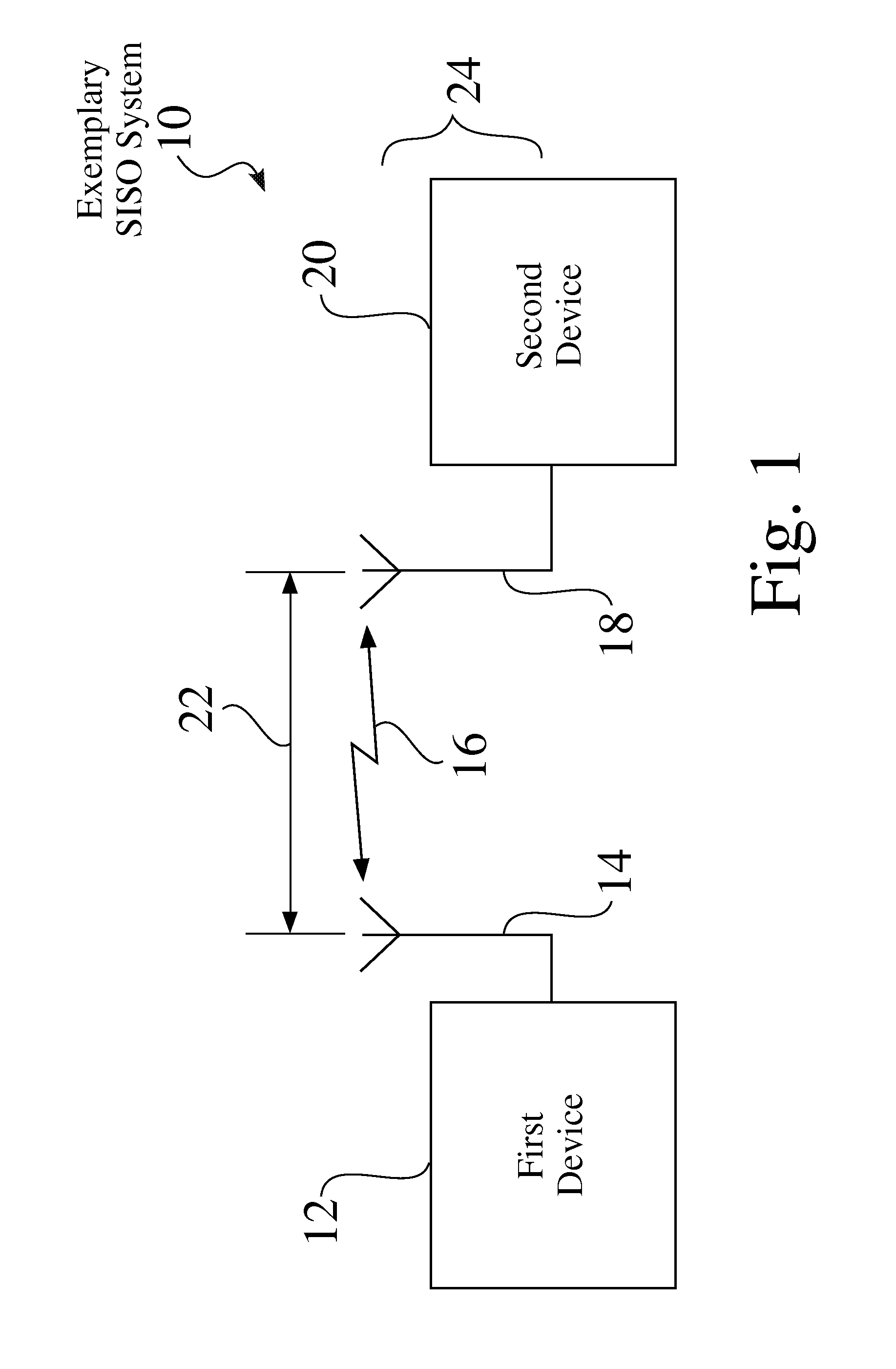
[0028]FIG. 1 is a simplified schematic view of an exemplary single input, single output (SISO) system 10. A first device 12, e.g. a transmitter 12, transmits a wireless signal 16 from an antenna 14. The wireless signal 16 is received at an antenna 18 associated with a second, receiving device 20, which processes the signal 16, such as using signal processing circuitry and a microprocessor. Both the transmitter 12 and the receiver 16 in the SISO system 10 seen in FIG. 1 have a single antenna 14,18, and operate to either send or receive a single signal 16.

[0029]In the exemplary SISO system 10 seen in FIG. 1, one or both of the devices 12, 20 may be moved in relation to the other device 20,12, such that the distance 22 between the antennas 14,18 may vary, such as between transmissions of wireless signals 16, and / or during a transmission of a wireless signal 16. While the distance 22 changes the time of flight of the wireless signal 16, the second device 20 can still receive and process...


PUM


Abstract

Systems, processes, and structures provide near-field transmit power measurement for MIMO wireless devices (DUT), such as for any of product development, product verification, and / or production testing. A test signal, such as comprising a pulse train signal, is provided to a MIMO device under test (DUT), wherein portions of the test signal controllably steered and sequentially transmitted from each of the device antennas, to one or more test antennas that are positioned in close proximity to the MIMO DUT. The near-field power of the received test signals is measured, to quickly and efficiently determine if one or more data streams of the MIMO DUT has a problem.

Description

BACKGROUND OF THE INVENTION[0001]1. Technical Field[0002]The invention relates generally to testing structures and processes for wireless or RF (radio frequency) communications systems. More particularly, the invention relates to structures and processes that provide near-field transmit power measurement of MIMO wireless devices and systems.[0003]2. Description of the Background Art[0004]Single-input single-output (SISO) wireless devices have been developed and implemented for many years, to transmit and / or receive desired signals to / from other elements, to provide wireless connectivity and communication between devices in a wireless network, such as in a wireless PAN (personal area network), a wireless LAN (local area network) a wireless WAN (wide area network), a cellular network, or virtually any other radio network or system. Such SISO devices may operate over a wide variety of frequency bands, such as but not limited to 2.4 GHz and 5.0 GHz bands. Test systems and standardized t...

Claims


Application Information

Patent Timeline
Patent Type & Authority Patents(United States)
IPC IPC(8): H04B7/02
CPCH04B5/0043H04B7/0413H04B17/10H04B17/0002
Inventor EMMANUEL, JOSEPH AMALAN ARULHUMMEL, JONATHAN M.
Owner NETGEAR INC
Why Eureka
Try Eureka