Method and device for manufacturing a primary preform for optical fibres

a manufacturing method and optical fibre technology, applied in glass production, glass making apparatus, manufacturing tools, etc., can solve the problem of limited layer thickness of glass layer additionally applied to the primary preform, and achieve the effect of reducing the deviation of the refractive index of deposited glass, increasing the usable length of the primary preform, and reducing the thickness of the optical taper

Active Publication Date: 2014-09-09
DRAKA COMTEQ BV
View PDF10 Cites 2 Cited by
  • Summary
  • Abstract
  • Description
  • Claims
  • Application Information

AI Technical Summary

Benefits of technology

[0043]Another object of the present invention is to provide a method and a device for manufacturing a primary preform in which deviations of the longitudinal refractive index profile from a desired refractive index profile are minimized.
[0060]This embodiment makes it possible to set an optimum temperature profile along the deposition length of the hollow glass substrate tube for each preform layer in situations where preform layers with mutually different dopant levels are used.

Problems solved by technology

Consequently, the layer thickness of the glass layer additionally applied to the primary preform is limited by the thickness of the preform layers being formed by means of the internal vapour deposition process.

Method used


Image

  • Method and device for manufacturing a primary preform for optical fibres
  • Method and device for manufacturing a primary preform for optical fibres
  • Method and device for manufacturing a primary preform for optical fibres

Examples


example

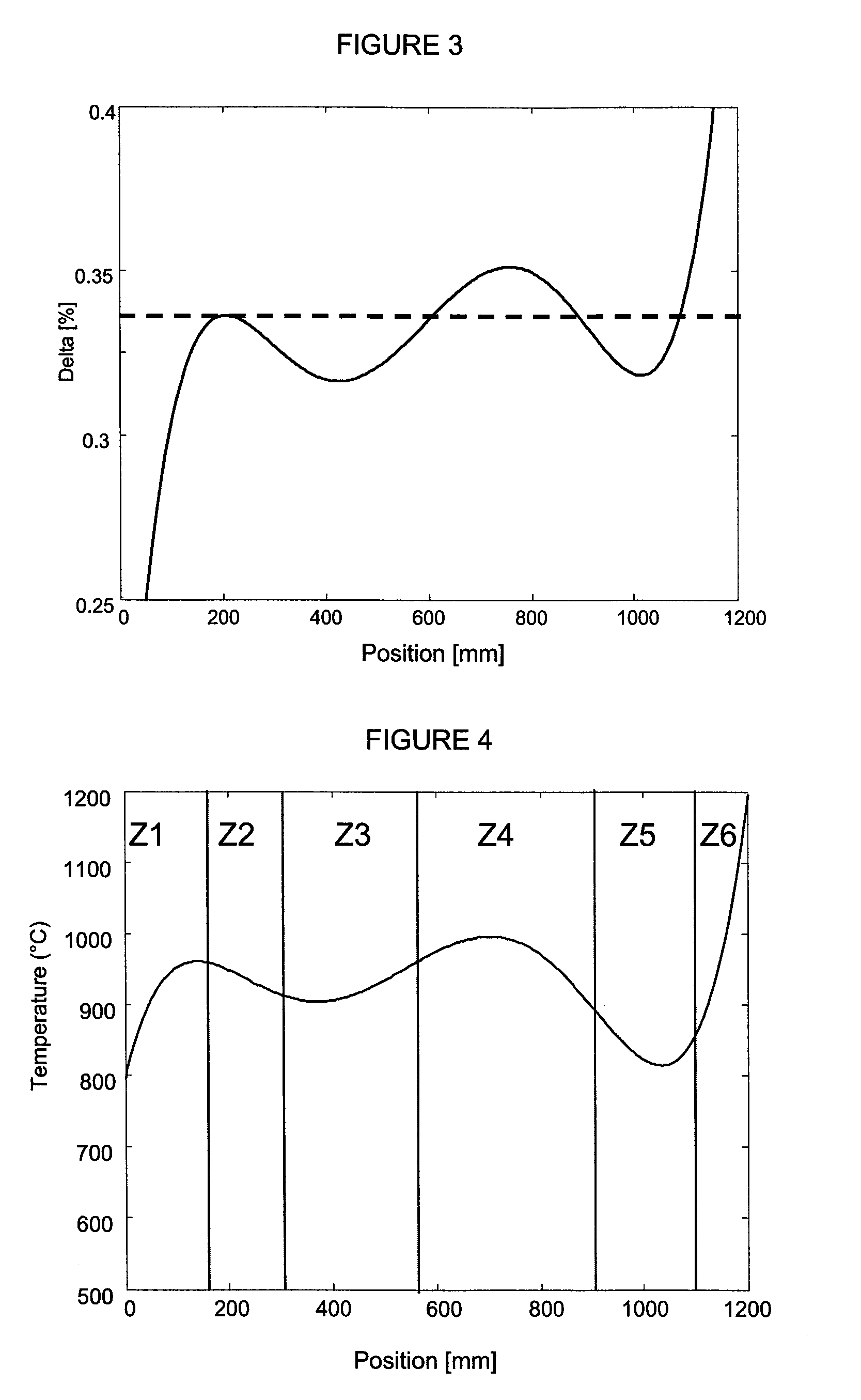
[0089]Based on the longitudinal refractive index profile shown in FIG. 3, a (longitudinal) temperature profile is subsequently determined for the furnace 1, using a computer model, which temperature profile is used to reduce the deviations of the refractive index (expressed as Δ%) from a desired value, which is 0.335% in the present example.

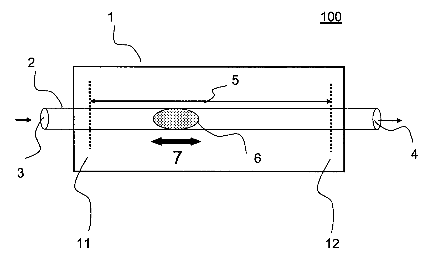
[0090]The thus determined temperature profile is shown in FIG. 4, in which the furnace temperature is shown on the vertical axis and the position in the primary preform is shown on the horizontal axis. The position in the primary preform shown in FIG. 3 corresponds to the position of the hollow glass substrate tube 2 in FIG. 4.

[0091]The vertical full lines in FIG. 4 correspond to the six temperature zones Z1-Z6. Thus, temperature zone Z2 starts at a position of 160 mm and ends at a position of 310 mm, zone Z3 starts at a position of 310 mm and ends at a position of 575 mm, etc. It is noted that the present invention is not limited to an embodimen...


PUM

PropertyMeasurementUnit
velocityaaaaaaaaaa
velocityaaaaaaaaaa
temperatureaaaaaaaaaa

Abstract

A method for manufacturing a primary preform for optical fibers using an internal vapor deposition process including the steps of providing a substrate tube having supply and discharge sides, surrounding at least part of the tube by a furnace, supplying glass-forming gases to the interior of the tube via the supply side, creating a reaction zone with conditions such that deposition of glass will take place on the inner surface of the tube, and moving the reaction zone back and forth along the length of the tube between reversal points near the supply and discharge sides to form one or more preform layers on the inner surface of the tube, wherein both reversal points are surrounded by the furnace.

Description

TECHNICAL FIELD AND BACKGROUND OF THE INVENTION[0001]The present invention relates to a method for manufacturing a primary preform for optical fibres using an internal vapour deposition process, comprising the steps of:[0002]i) providing a hollow glass substrate tube having a supply side and a discharge side,[0003]ii) surrounding at least part of the hollow glass substrate tube by a furnace,[0004]iii) supplying glass-forming gases to the interior of the hollow glass substrate tube via the supply side thereof,[0005]iv) creating a reaction zone with conditions such that deposition of glass will take place on the inner surface of the hollow glass substrate tube, and[0006]v) moving the reaction zone back and forth along the length of the hollow glass substrate tube between a reversal point located near the supply side and a reversal point located near the discharge side of the hollow glass substrate tube so as to form one or more preform layers on the inner surface of the hollow glass s...

Claims


Application Information

Patent Timeline
Patent Type & Authority Patents(United States)
IPC IPC(8): C03B37/018
CPCC03B37/0183C03B37/01815Y02P40/57
Inventor HARTSUIKER, JOHANNES ANTOONMILICEVIC, IGORVAN STRALEN, MATTHEUS JACOBUS NICOLAASKUIJPERS, ERIC ALOYSIUS
Owner DRAKA COMTEQ BV
Why Eureka
Try Eureka