Ventilation member

a technology of ventilation member and gas permeation area, which is applied in the direction of electrical apparatus casing/cabinet/drawer, electrical apparatus, lighting and heating apparatus, etc., can solve the problems of insufficient gas permeation of the attachment area of the ventilation member, the limit of further gas permeation quantity, and the inability to ensure the attachment area in some cases, so as to achieve sufficient gas permeation quantity, and increase the gas permeable area

Active Publication Date: 2014-09-09
NITTO DENKO CORP
View PDF16 Cites 9 Cited by
  • Summary
  • Abstract
  • Description
  • Claims
  • Application Information

AI Technical Summary

Benefits of technology

[0020]The support body of the first ventilation member of the present invention is provided with, at the edge of the opening closed by the gas permeable membrane, the first angled protrusion and the second angled protrusion. Since the first angled protrusion and the second angled protrusion are provided respectively in the first region and the second region facing each other with the opening located therebetween, they face each other with the opening located therebetween. Joined onto the first angled protrusion and the second angled protrusion thus configured, the gas permeable membrane has a pleat shape or wave shape with peaks and troughs. In the first ventilation member of the present invention, since the gas permeable membrane has a pleat shape or wave shape as just described, it is possible to increase a gas permeable area without increasing the attachment area, and thereby to increase the gas permeation quantity.
[0021]In the first ventilation member of the present invention, the gas permeable area is larger than that of a ventilation member having a sheet-like gas permeable membrane, and both ends of the troughs of the gas permeable membrane are open. Thus, even when the gas permeable membrane is disposed parallel to a horizontal plane and a water droplet is put thereon, there is, unlike in the case of a sheet-like gas permeable membrane, low possibility of the gas permeable area being covered with the water droplet. Furthermore, the water droplets accumulated at the troughs can flow out from the both ends of the troughs. In this way, the first ventilation member of the present invention can ensure a sufficient gas permeation quantity even when a water droplet is put on the gas permeable membrane.
[0022]In the second ventilation member of the present invention, the gas permeable membrane disposed inside the through hole of the support body has a pleat shape or a wave shape. Thus, in the second ventilation member of the present invention, it is possible to increase the gas permeable area without increasing the attachment area, and thereby to increase the gas permeation quantity. Moreover, in the second ventilation member of the present invention, the gas permeable membrane is disposed so as to be accommodated inside the through hole. Therefore, the second ventilation member of the present invention can be reduced further in size while ensuring a large gas permeation quantity.

Problems solved by technology

However, in a ventilation member with such a structure, there is a limitation in increasing further the gas permeation quantity because the gas permeable membrane has a sheet-like shape.
In components and devices that need internal pressure adjustment, an attachment area in which a ventilation member is to be attached cannot be ensured sufficiently in some cases.
Particularly, automobile lamps have a problem in that a lamp lens surface is fogged with water condensation.
However, since the area in which the ventilation member can be attached is limited, there has been a limitation in achievable gas permeation quantity.

Method used


Image

  • Ventilation member
  • Ventilation member
  • Ventilation member

Examples


embodiment 1

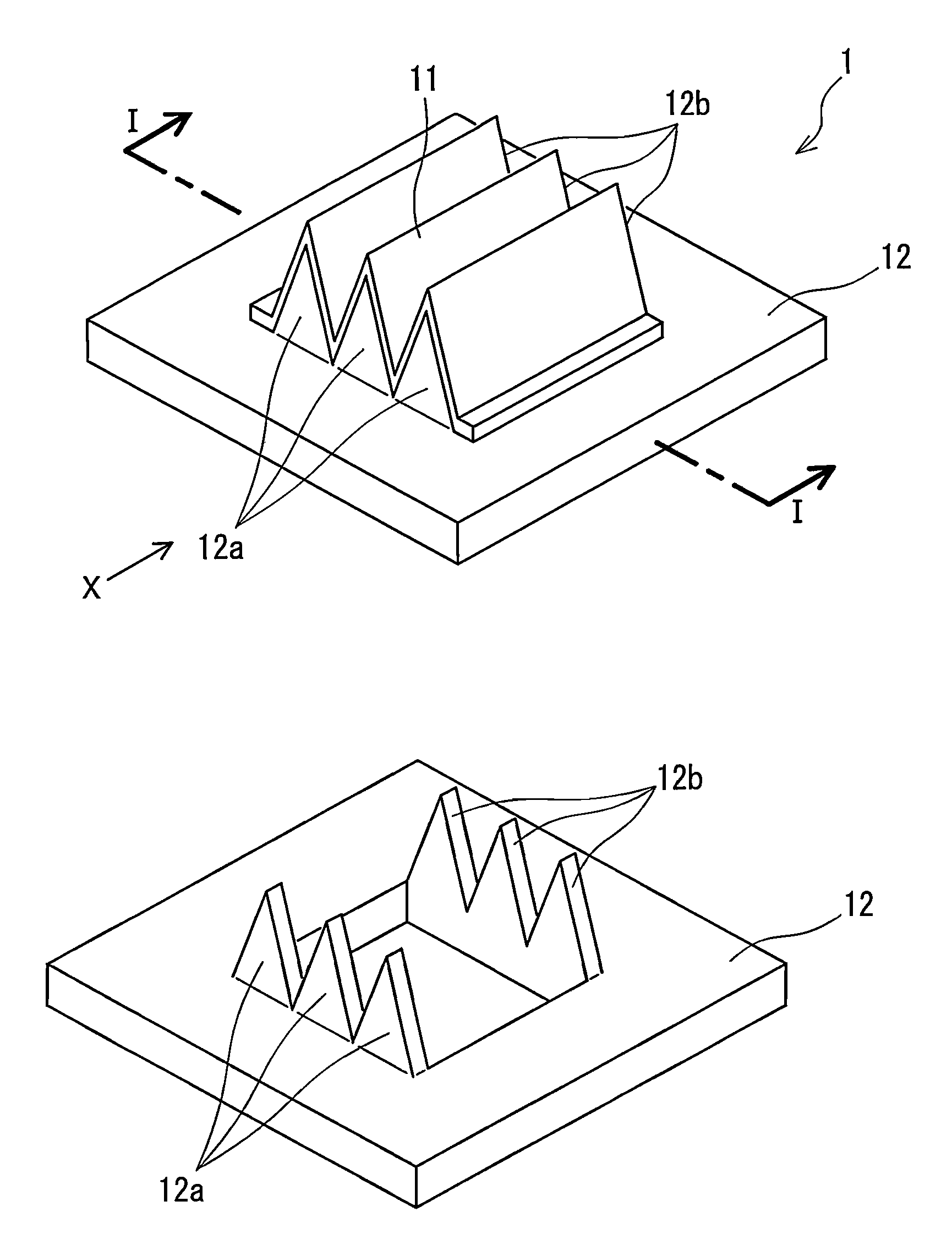
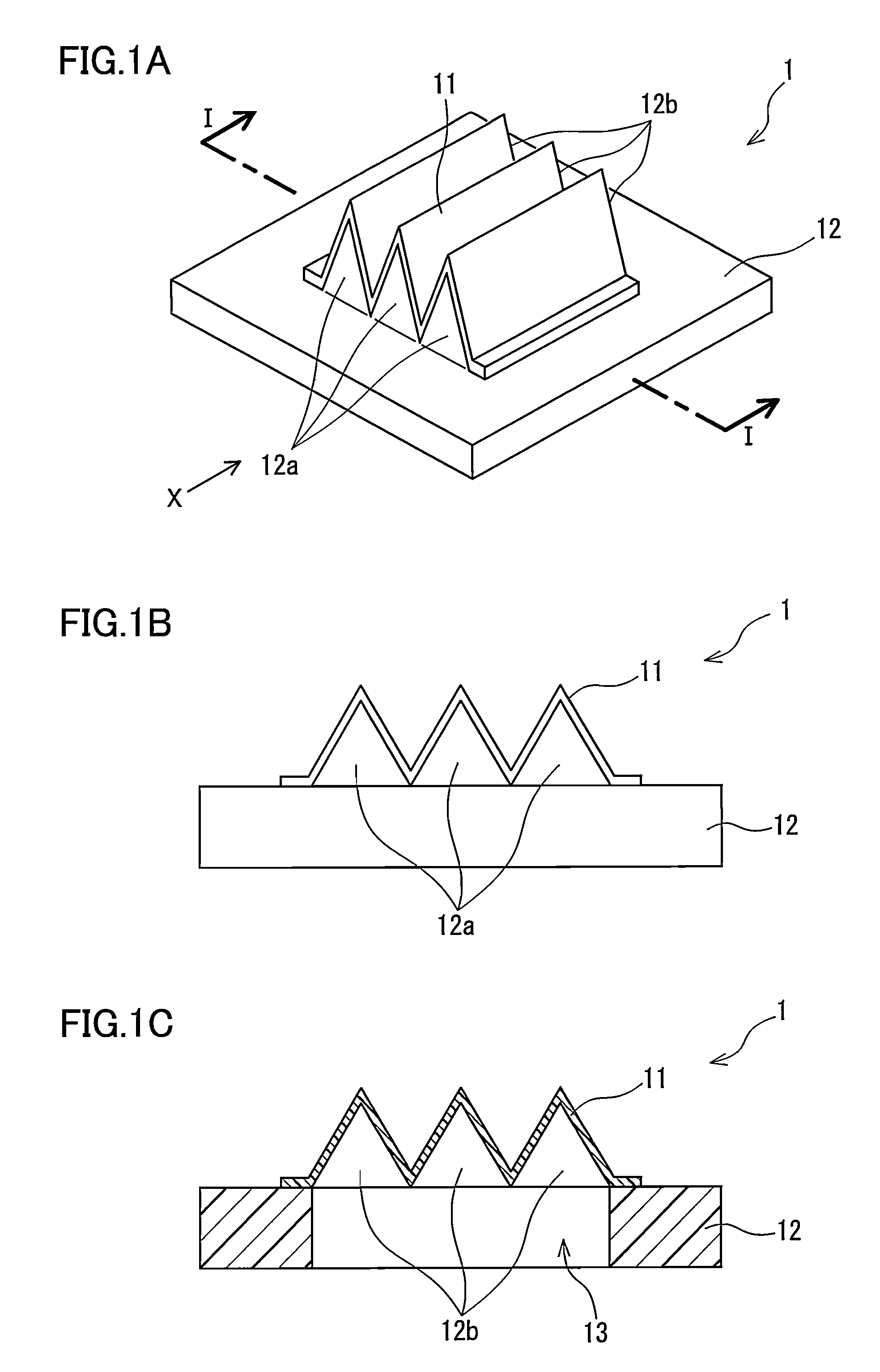
[0038]FIG. 1A is a perspective view showing the structure of a ventilation member 1 in Embodiment 1 of the present invention. FIG. 1B is a side view of the ventilation member 1 shown in FIG. 1A, viewed from the X direction. FIG. 1C is a cross-sectional view of FIG. 1A, taken along the line I-I.

[0039]The ventilation member 1 of the present embodiment includes a waterproof gas permeable membrane 11, and a support body 12 having a through hole 13. One opening of the through hole 13 is closed by the gas permeable membrane 11.

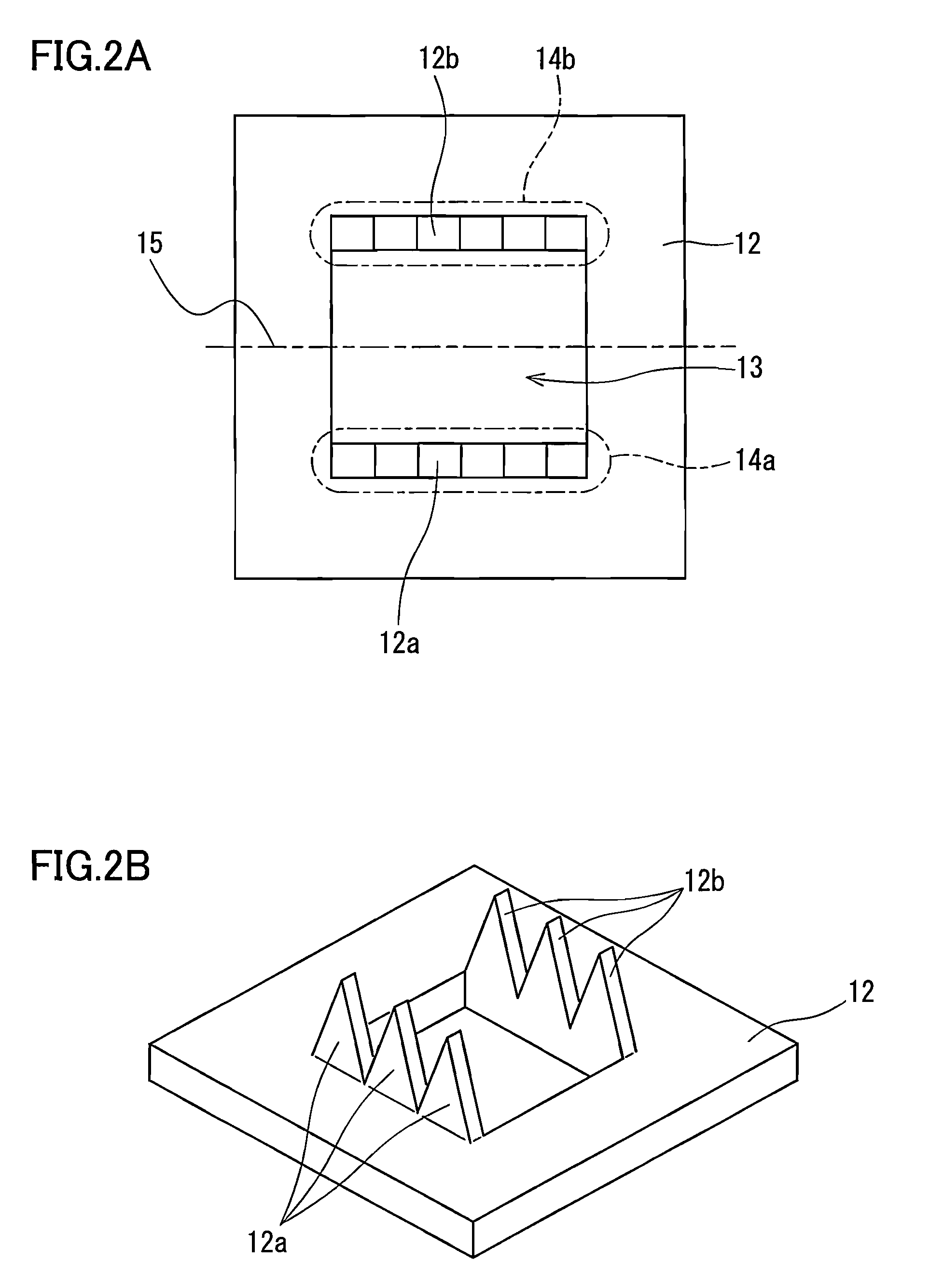
[0040]The shape of the support body 12 is described with reference also to FIG. 2A and FIG. 2B. The support body 12 includes, at an edge of the opening closed by the gas permeable membrane 11, a first region 14a and a second region 14b facing each other with the opening located therebetween. A first angled protrusion 12a in which a peak and a trough are arranged alternately along the edge of the opening is provided in the first region 14a. A second angled protrusion...

embodiment 2

[0061]With reference to FIG. 4A, FIG. 4B, FIG. 5A, and FIG. 5B, structural examples of a ventilation member in Embodiment 2 of the present invention are described. The ventilation member of the present embodiment is different from the ventilation member 1 of Embodiment 1 in that the support body has a shape to be fitted to an attachment portion of a housing to which the ventilation member is to be attached, that is, the support body has a shape that enables so-called one-touch attachment to the housing as a mating member. Since the rest of the configuration is the same as that of the ventilation member 1 of Embodiment 1, detailed description thereof is omitted in the present embodiment.

[0062]As shown in FIG. 4A, a ventilation member 4 of the present embodiment includes a waterproof gas permeable membrane 41, and a circular cylindrical support body 42 having a through hole 42a. One opening of the through hole 42a is closed by the gas permeable membrane 41. The ventilation member 4 fu...

embodiment 3

[0067]FIG. 8 is a cross-sectional view showing one structural example of a ventilation member 8 in Embodiment 3 of the present invention. The ventilation member 8 shown in FIG. 8 includes a support body 81 having a through hole 82, and a gas permeable membrane 83 disposed inside the through hole 82. In the present embodiment, the support body 81 is a cylindrical body. The through hole 82 of the support body 81 serves as a gas passage to the inside and outside of a housing when the ventilation member 8 is attached to the housing. The gas permeable membrane 83 is joined to an inner wall surface of the through hole so as to close the through hole 82, and has a pleat shape. That is, the gas permeable membrane 83 is accommodated inside the through hole 82 of the support body 81 while being folded in a pleat shape.

[0068]Desirably, sealing is provided between a periphery of the gas permeable membrane 83 and the inner wall surface of the through hole of the support body 81. The sealing betw...


PUM

PropertyMeasurementUnit
heightaaaaaaaaaa
temperatureaaaaaaaaaa
falling angleaaaaaaaaaa

Abstract

The ventilation member of the present invention includes a waterproof gas permeable membrane (11), and a support body (12) having a through hole (13). One opening of the through hole (13) is closed by the gas permeable membrane (11). The support body (12) includes, at an edge of the opening closed by the gas permeable membrane (11), a first region and a second region facing each other with the opening located therebetween. A first angled protrusion (12a) in which a peak and a trough are arranged alternately along the edge of the opening is provided in the first region, and a second angled protrusion (12b) in which a peak and a trough are arranged alternately along the edge of the opening is provided in the second region. The gas permeable membrane (11) is joined onto the first angled protrusion (12a) and the second angled protrusion (12b), and has a pleat shape or a wave shape in which a peak and a trough are arranged alternately along shapes of the first angled protrusion (12a) and the second angled protrusion (12b).

Description

TECHNICAL FIELD[0001]The present invention relates to a ventilation member used for adjusting the internal pressure of various housings of, for example, automobile electrical components, such as automobile lamps and ECUs (Electrical Control Units), electric toothbrushes, shavers, and outdoor lighting devices.BACKGROUND ART[0002]In many cases, various housings of, for example, automobile electrical components, electric toothbrushes, shavers, and outdoor lighting devices are provided with a ventilation hole for the purpose of, for example, preventing deformation and burst of the housings due to temperature difference between inside and outside of the housings. In the case where the housings are provided with a ventilation hole, ventilation members including various waterproof gas permeable membranes are used in order to prevent water and dust from entering into the housings (see Patent Literatures 1 to 3).[0003]For example, Patent Literature 3 discloses a ventilation member fabricated...

Claims


Application Information

Patent Timeline
Patent Type & Authority Patents(United States)
IPC IPC(8): B01D53/22B01D71/36B01D69/10F21S8/10F21V31/03
CPCF21V31/03F21S48/337F21S48/335F21S45/33F21S45/37H05K5/0215H05K5/0216F21V29/85F21S45/50F21S45/49H05K5/0213
Inventor FURUUCHI, KOUJIYANO, YOUZOU
Owner NITTO DENKO CORP
Why Eureka
Try Eureka