Multiple electromagnetic valve

a technology of electromagnetic valves and electromagnetic valves, applied in the direction of valve housings, valve operating means/release devices, transportation and packaging, etc., can solve the problems of increased height or width in the top-bottom direction of the valve body, difficulty in forming flow paths connecting the valve holes and ports, and increased height and height of the valve body. , the effect of reducing the width of the valve body

Active Publication Date: 2014-09-16
SMC CORP
View PDF18 Cites 4 Cited by
  • Summary
  • Abstract
  • Description
  • Claims
  • Application Information

AI Technical Summary

Benefits of technology

[0007]An object of the present invention is to provide a multiple electromagnetic valve in which a plurality of valve mechanisms is arranged reasonably, and thereby further reduction in size is achieved and the formation of flow paths is facilitated.
[0015]According to the present invention having the above-described structure, valve holes in a plurality of valve mechanisms is formed close to each other in a reasonable arrangement in the valve body. Therefore, compared to the case where the valve holes are arranged exactly in a straight line in the top-bottom direction or left-right direction, the width, height, and the like of the valve body can be reduced significantly, and further reduction in size of the electromagnetic valve can be achieved. In addition, in spite of the reduced width of the valve body, it is easy to form flow path holes connecting the valve holes and ports in the valve body around the upper and lower valve holes, and there is no necessity to greatly bend the flow path holes in order to go around the valve holes.

Problems solved by technology

Because a plurality of valve mechanisms is arranged in a straight line in the top-bottom direction or the left-right direction, in the case where for example, three or more valve mechanisms are incorporated, the size in the top-bottom direction (the height) or the size in the left-right direction (the width) of the valve body increases, and the handling and installation may become difficult.
Therefore, it is difficult to form flow paths connecting the valve holes and ports.

Method used


Image

  • Multiple electromagnetic valve
  • Multiple electromagnetic valve
  • Multiple electromagnetic valve

Examples


first embodiment

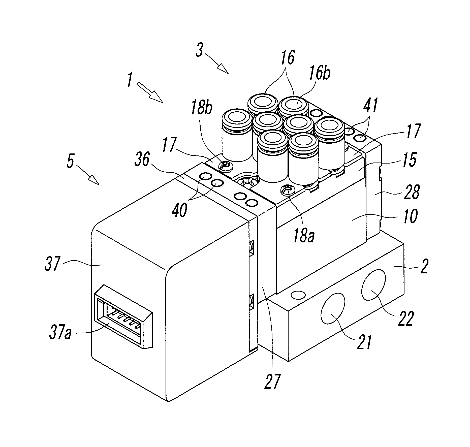
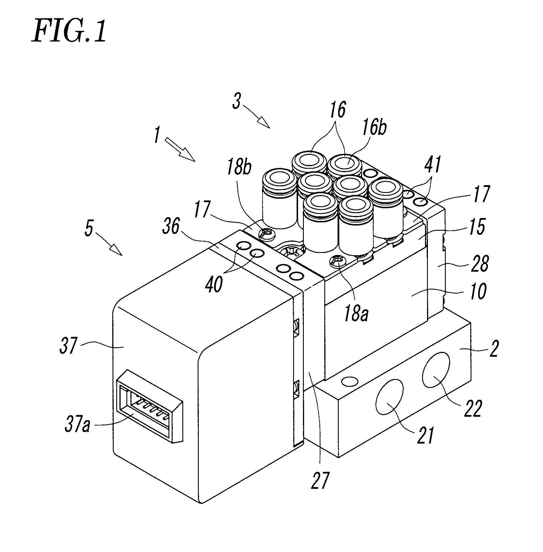
[0028]FIGS. 1 to 7 show a multiple electromagnetic valve according to the present invention. The multiple electromagnetic valve 1 is mounted on a manifold base 2.

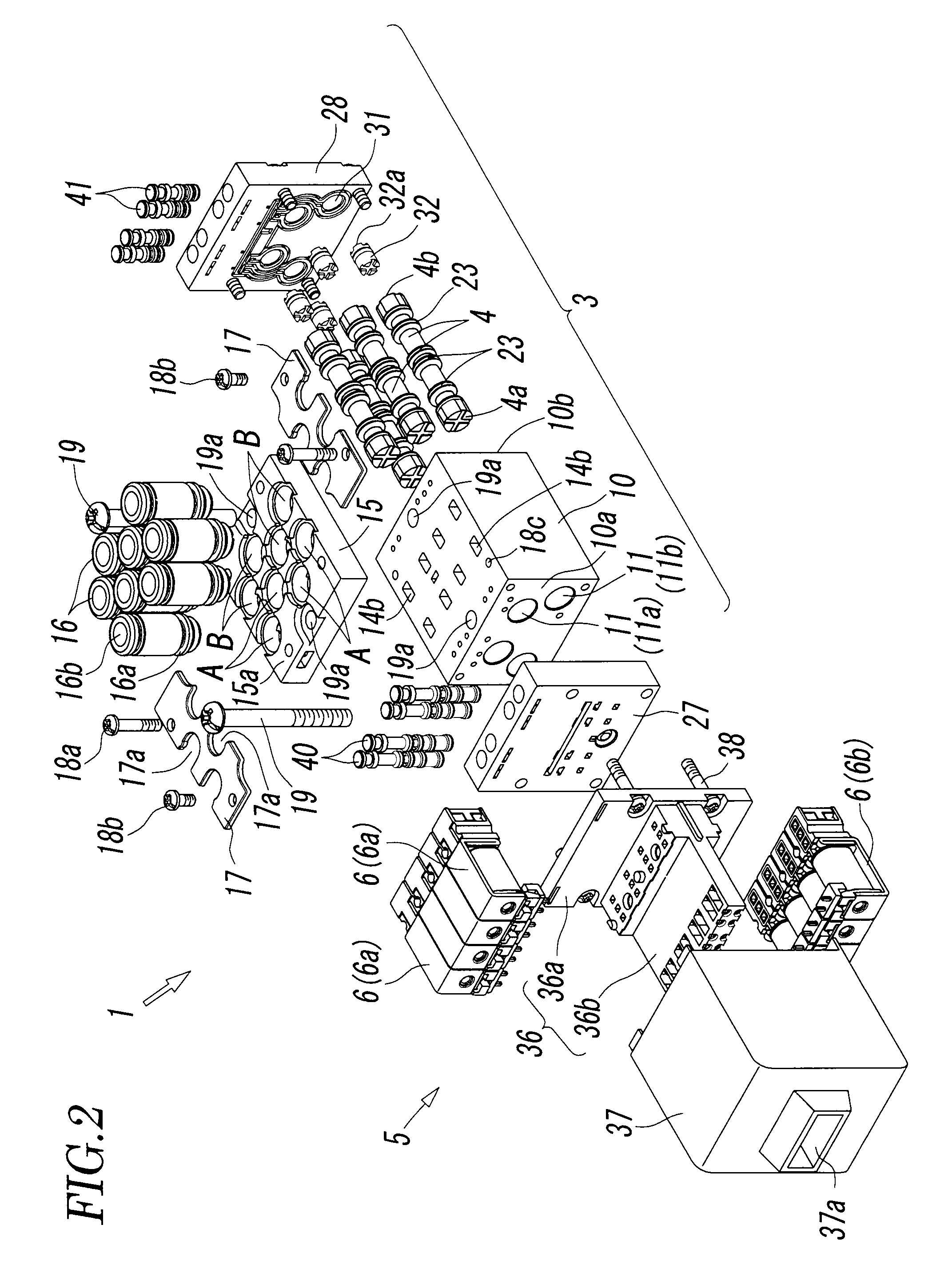
[0029]The multiple electromagnetic valve 1 has a plurality of sets of valve mechanisms that is of the same form and that have a valve structure as a five-port electromagnetic valve. The multiple electromagnetic valve 1 includes a main valve portion 3 having spools 4 that switch flow paths for main fluid, and a pilot operating portion 5 having solenoid operated pilot valves 6 that drive the spools 4 with pilot fluid. In this embodiment, both the main fluid and pilot fluid are compressed air.

[0030]As can be seen from FIGS. 2 and 4, the main valve portion 3 has a rectangular block-like valve body 10. Inside the valve body 10, a number of valve holes 11 that correspond to the number of the valve mechanisms are formed parallel to each other. Both ends of each valve hole 11 open on a first end face 10a and a second end face 10b o...

third embodiment

[0072]FIGS. 11 and 12 show the present invention. The third embodiment differs in the number and arrangement of the valve holes 11 and the output ports A and B from both the first embodiment and second embodiment.

[0073]That is to say, as shown in FIG. 12, six valve holes 11 are formed inside the valve body 10, and these valve holes 11 are arranged such that four valve holes 11a are located in the upper tier and two valve holes 11b are located in the lower tier. Of the four valve holes 11a in the upper tier, the distance X1 between the centers of the two valve holes 11a in the left half and the distance X2 between the centers of the two valve holes 11a in the right half are equal to each other, and the two valve holes 11b in the lower tier occupy a position midway between the two valve holes 11a in the left half of the upper tier and a position midway between the two valve holes 11a in the right half. Of the four valve holes in the upper tier, the distance X3 between the centers of t...


PUM


Abstract

A multiple electromagnetic valve includes a main valve portion in which four or more valve holes are formed parallel to each other inside a valve body, and a spool for switching flow paths is placed in each valve hole, and a pilot operating portion having solenoid-operated pilot valves that drive the spools with pilot fluid. The valve holes are disposed inside the valve body in two upper and lower tiers. A plurality of valve holes belongs in each of the upper tier and lower tier. The valve holes in the upper tier and the valve holes in the lower tier occupy different positions in the width direction of the valve body. The valve holes in the upper tier and the valve holes in the lower tier partially overlap each other in the plan view of the valve body.

Description

BACKGROUND OF THE INVENTION[0001][1] Field of the Invention[0002]The present invention relates to a multiple electromagnetic valve in which a plurality of valve mechanisms is incorporated in a valve body.[0003][2] Description of the Related Art[0004]A multiple electromagnetic valve in which a plurality of valve mechanisms is incorporated in a valve body is known as disclosed, for example, in Patent Literature 1 (Japanese Unexamined Utility Model Registration Application Publication No. 61-106672), Patent Literature 2 (Japanese Unexamined Patent Application Publication No. 8-178105), and Patent Literature 3 (Japanese Unexamined Patent Application Publication No. 9-32941). Such a multiple electromagnetic valve has the advantage of being compact and therefore space-saving compared to the case where the same number of independent electromagnetic valves as the valve mechanisms are arranged.[0005]However, the conventional multiple electromagnetic valve is such a multiple electromagnetic v...

Claims


Application Information

Patent Timeline
Patent Type & Authority Patents(United States)
IPC IPC(8): F16K11/24F15B13/08F16K27/00
CPCF16K27/003F15B13/0842Y10T137/87885F15B13/043F16K11/07
Inventor KATO, HISATAKA
Owner SMC CORP
Why Eureka
Try Eureka