Medium stocking apparatus
a stocking apparatus and medium-sized technology, applied in the direction of instruments, apparatus for dispensing discrete objects, transportation and packaging, etc., can solve the problems of tape being torn off, troublesome maintenance work, and increasing the diameter of the tap
- Summary
- Abstract
- Description
- Claims
- Application Information
AI Technical Summary
Benefits of technology
Problems solved by technology
Method used
Image
Examples
first embodiment
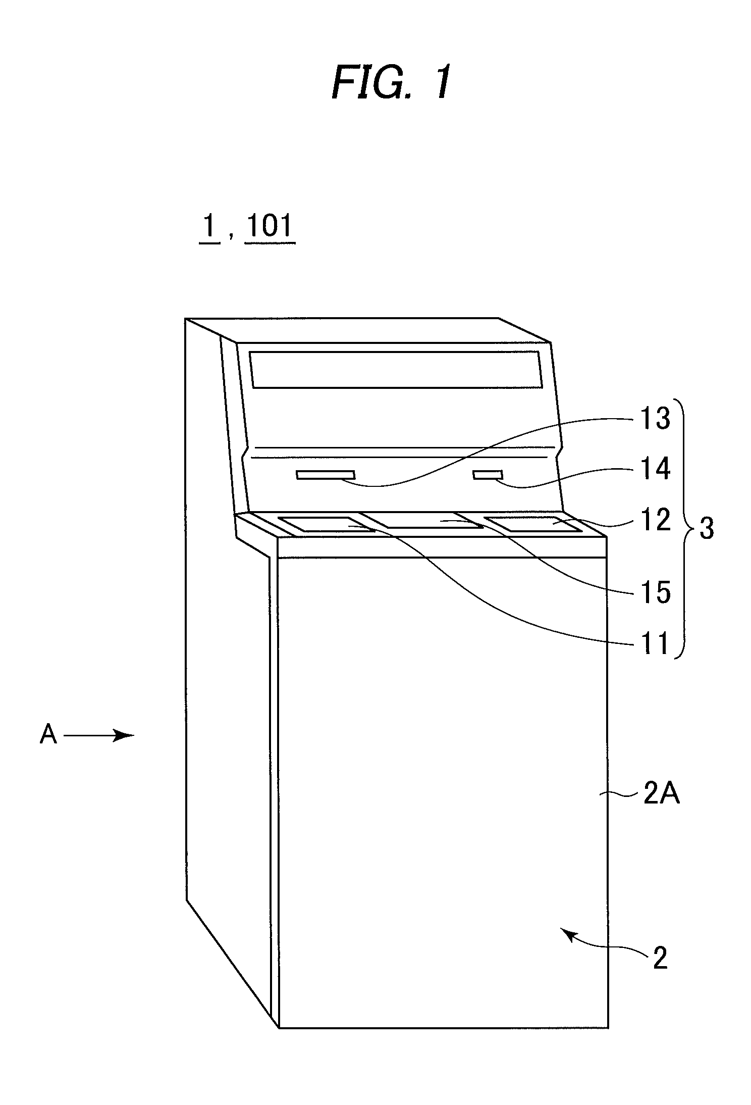
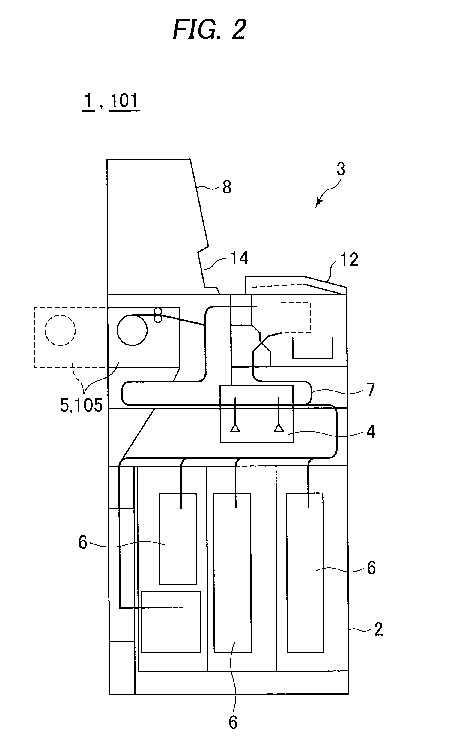
[0023]With reference to the accompanying drawings, the entire structure of a medium stocking apparatus according to the present invention will be described in detail. As shown in FIG. 1, an automated teller machine 1 is elementally constructed by a housing 2 to be served to conduct cash transactions with customers. The housing 2 is provided with a customer service section 3 in an area convenient for the customer standing in front of the machine to insert bills into the machine and operate its touch panel, i.e. an area across from the upper part of its foreside 2A to its top side.
[0024]The customer service section 3 is designed to directly handle cash, a bankbook and the like for the customer as well as imparting information on a transaction and receiving operational instructions, and is provided with a coin slot 11, a bill slot 12, a bankbook slot 13, a card slot 14 and a display console 15.
[0025]The coin slot 11 and the bill slot 12 are adapted for receiving coins and bills the cus...
second embodiment
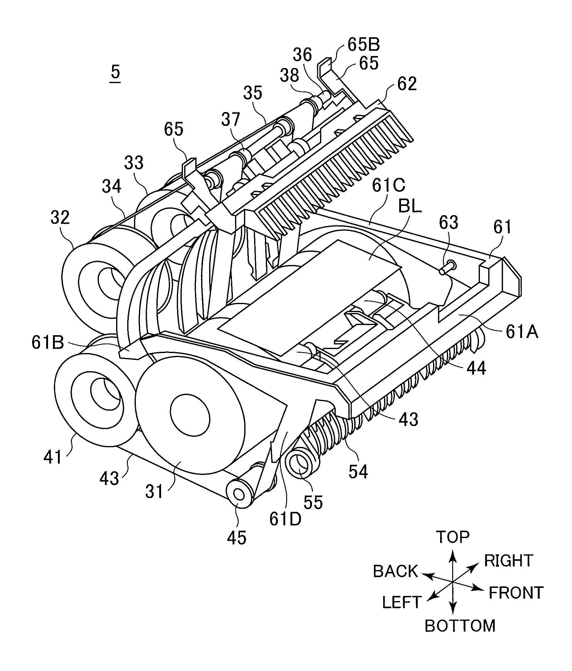
[0117]Specifically, the movable upper guide 151 of the second embodiment is arranged so that, as illustrated in FIG. 9, the upper guide base 162 lying anterior to the place contacting with the drum 31 can rotate in the open direction U1 with the upper drum guide 163 retained.
[0118]Furthermore, the upper guide base 162 is provided with the conveyance rollers 66, 67 and 68 on its under surface as with the upper guide base 62, and above the front side of the guide base 162 the pulley shaft 36, the upper tape pulleys 37, 38 and the lock lever 65 are fitted.
[0119]The above configuration can produce the following advantages.
[0120]In the temporary holding section 105 according to the second embodiment, the frame 161 and the upper guide base 162 are rotatably joined by the retraction shaft 64 in the vicinity of the upper part of the place where the movable upper guide 151 comes in contact with the drum 31, and as in the case with the first embodiment, the engagement groove 65A of the lock l...
PUM
| Property | Measurement | Unit |
|---|---|---|
| angles | aaaaa | aaaaa |
| angles | aaaaa | aaaaa |
| width | aaaaa | aaaaa |
Abstract
Description
Claims
Application Information
 - R&D
- Intellectual Property
- Life Sciences
- Materials
- Tech Scout
- Unparalleled Data Quality
- Higher Quality Content
- 60% Fewer Hallucinations
Browse by: Latest US Patents, China's latest patents, Technical Efficacy Thesaurus, Application Domain, Technology Topic, Popular Technical Reports.
© 2025 PatSnap. All rights reserved.Legal|Privacy policy|Modern Slavery Act Transparency Statement|Sitemap|About US| Contact US: help@patsnap.com


