Electromagnetically operatable valve

a valve and electromagnetic technology, applied in the direction of magnets, machines/engines, magnets, etc., can solve the problems of inability to use integral joining methods such as welding, disadvantages of thermal distortion, etc., and achieve the effects of simple and cost-effective valve assembly, increased stability in the solenoid area, and simple, reliable manner

Inactive Publication Date: 2014-09-16
ROBERT BOSCH GMBH
View PDF15 Cites 2 Cited by
  • Summary
  • Abstract
  • Description
  • Claims
  • Application Information

AI Technical Summary

Benefits of technology

[0004]The electromagnetically operatable valve according to the present invention has the advantage that a simplified and cost-effective assembly of the valve is implementable because the non-magnetic intermediate part may be omitted. The bobbin advantageously assumes the additional function of magnetic isolation in the electromagnetic circuit and increases the stability in the area of the solenoid. Integral joining methods such as welding, which have the disadvantage of thermal distortion, are not used. Rather, particularly advantageous plastic-metal pressure bonds may be used which are applicable in a simple, very safe, and reliable manner. The system according to the present invention also has the advantage of a reduction of the structure-borne noise and thus of noise generation compared to known approaches.
[0005]It is advantageous in particular if the core and the armature-side flow guide element are secured by pressing them into the bobbin or into the insert surrounded by the bobbin and possibly connected to it. The plastic-metal pressure bonds may be produced in a particularly safe and reliable manner if sawtooth-like structures are provided in the overlapping areas of the bobbin or the insert and the core, as well as the flow guide element. In the pressed-in state of the core and the flow guide element in the bobbin or in the insert surrounded by the bobbin, the sawtooth-like structure of the core and the flow guide element matches the directly opposite surface of the bobbin or the insert surrounded by the bobbin in that the sawtooth-like structure penetrates the plastic and the plastic relaxes.

Problems solved by technology

Integral joining methods such as welding, which have the disadvantage of thermal distortion, are not used.

Method used


Image

  • Electromagnetically operatable valve
  • Electromagnetically operatable valve
  • Electromagnetically operatable valve

Examples


Embodiment Construction

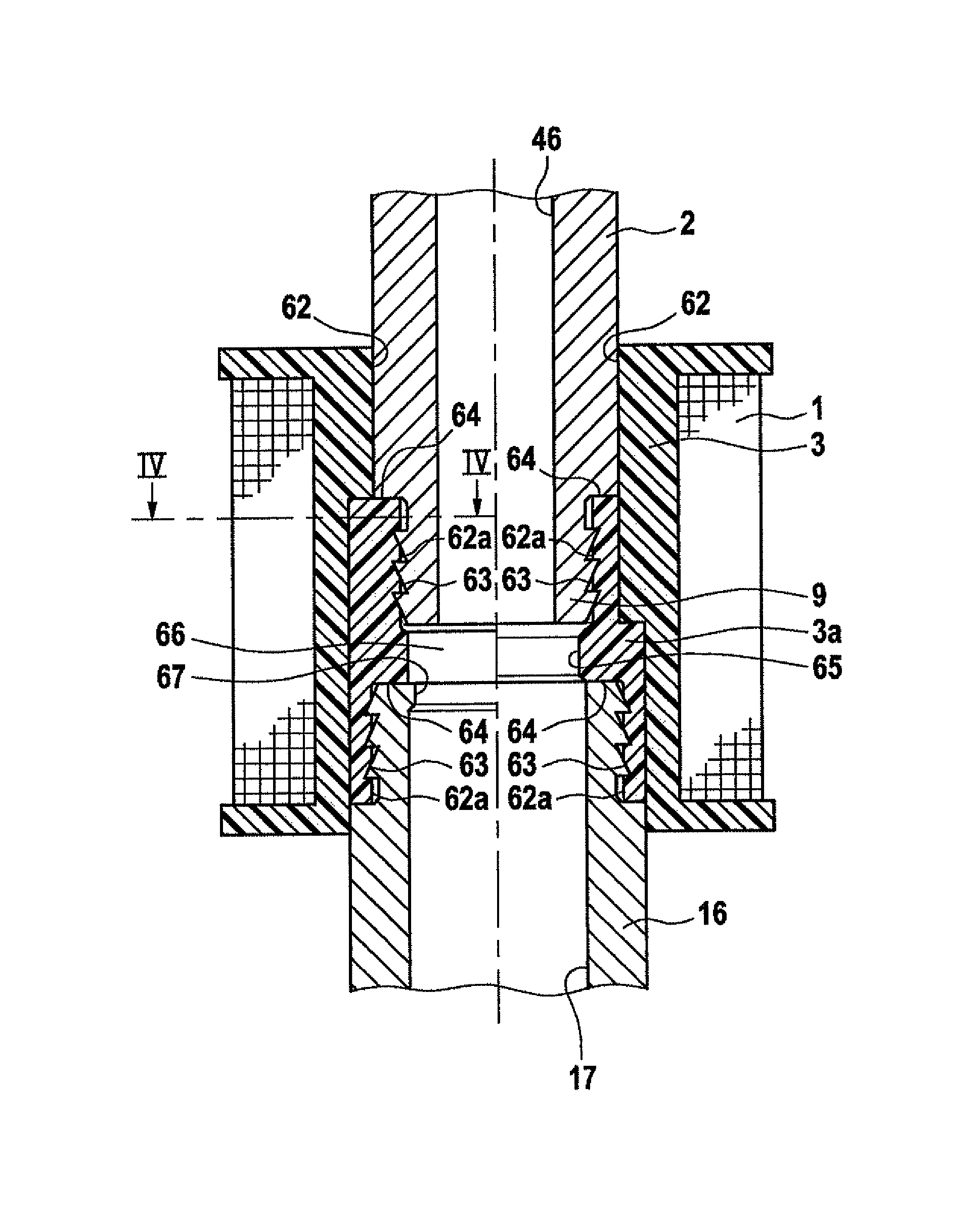
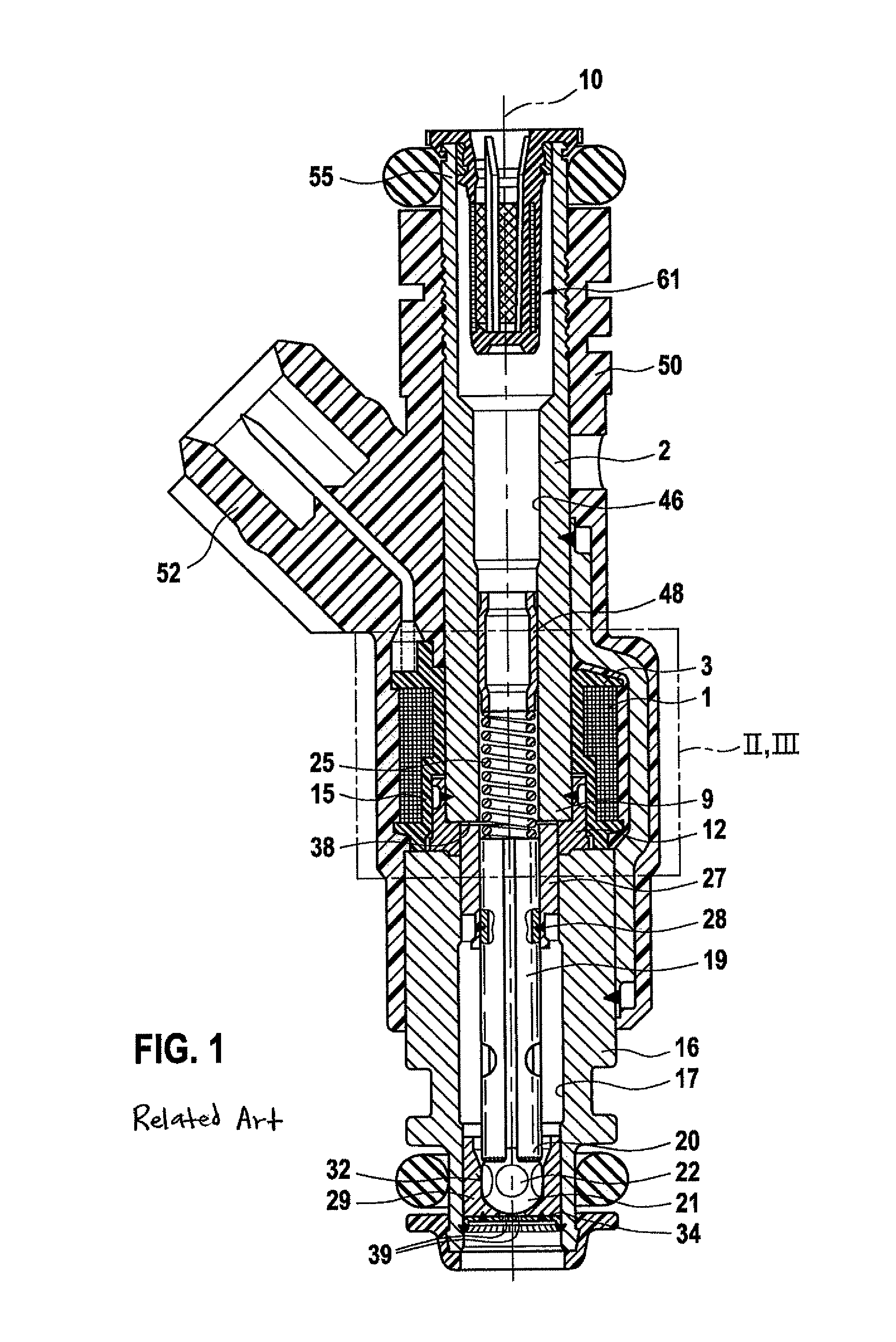
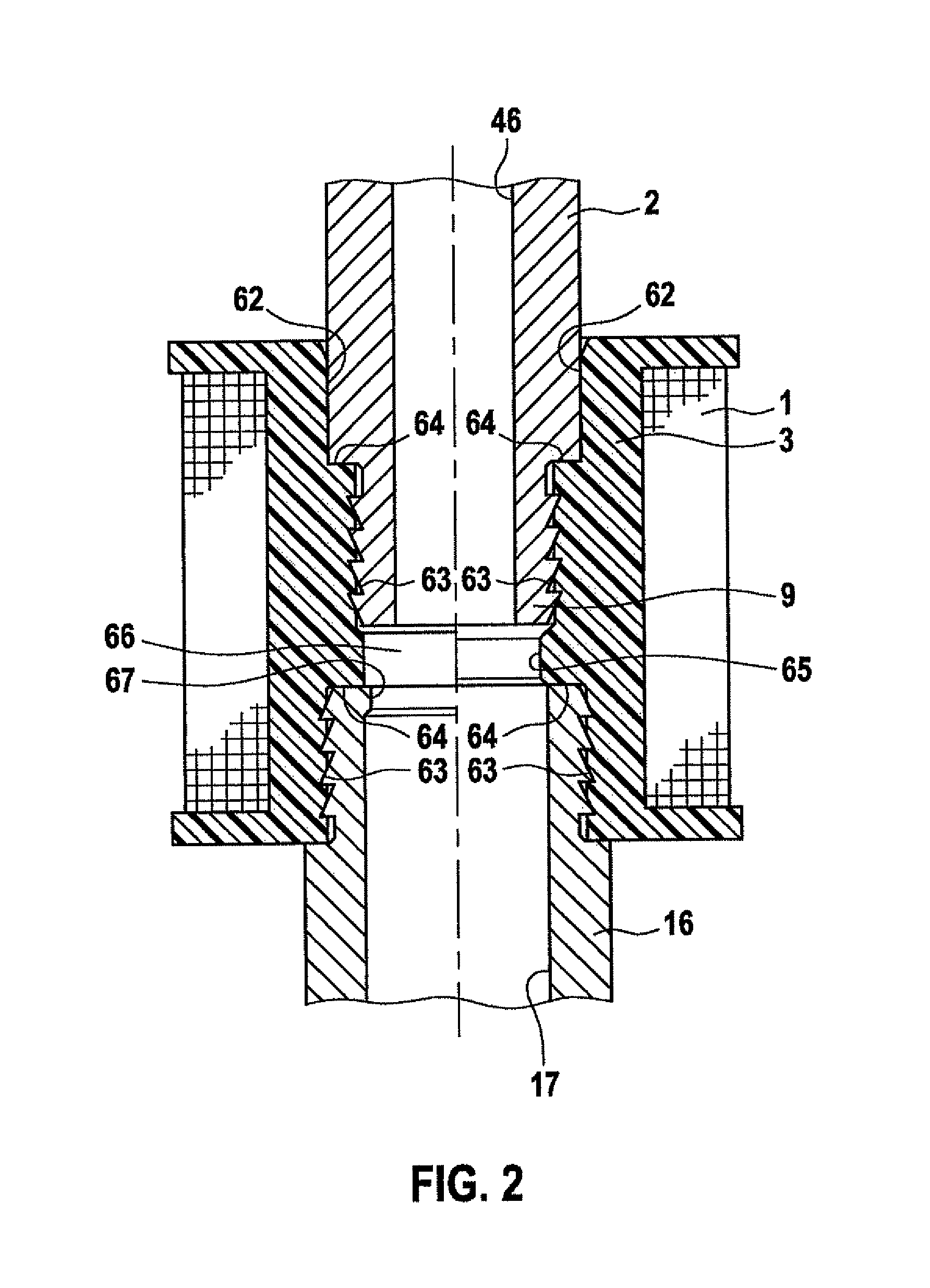
[0011]The electromagnetically operatable valve in the form of an injector for fuel injection systems of mixture-compressing, externally ignited internal combustion engines, shown in FIG. 1 as an example, has a core 2, which is designed here in the form of a tube surrounded by a solenoid 1, has a constant external diameter over its entire length, and functions as the internal pole and fuel inlet connecting piece. A bobbin 3 having steps in the radial direction accommodates a winding of solenoid 1 and, in combination with core 2, allows a compact design of the injector in the area of solenoid 1.

[0012]A tubular metallic non-magnetic intermediate part 12 is attached tightly, e.g., by welding, to a lower core end 9 of core 2 in such a way that it is concentric with a longitudinal valve axis 10, and thereby partially surrounds core end 9 axially. Stepped bobbin 3 partially surrounds core 2 and, with a step 15 of a larger diameter, axially surrounds intermediate part 12 at least partially....


PUM

PropertyMeasurementUnit
magneticaaaaaaaaaa
widthaaaaaaaaaa
stabilityaaaaaaaaaa

Abstract

The electromagnetically operatable valve, in particular a fuel injector for fuel injection systems of internal combustion engines, has a magnetic circuit having a core, a solenoid, a bobbin accommodating the winding of the solenoid, an armature, which operates a valve closing body cooperating with a fixed valve seat and is drawn against the core when the solenoid is excited, and having an armature-side flow guide element. The bobbin is designed and situated in such a way that magnetic isolation between the core and the armature-side flow guide element is ensured. The valve is suitable in particular for use in fuel injection systems of mixture-compressing, externally ignited internal combustion engines.

Description

BACKGROUND INFORMATION[0001]FIG. 1 shows a fuel injector known from the related art, having a conventional three-part design of an internal metallic flow guide part and a housing component. This internal valve tube is formed by an inlet connecting piece forming an internal pole, a non-magnetic intermediate part and a valve seat carrier accommodating a valve seat and is elucidated in greater detail in the description of FIG. 1.[0002]German Patent Application No. DE 44 21 935 describes such an electromagnetically operatable valve in the form of a fuel injector. The internal valve tube forms the basic skeleton of the entire injector and has an essential supporting function in its entirety for the three individual components. The non-magnetic intermediate part is tightly and fixedly connected to both the inlet connecting piece and the valve seat carrier by welds. The windings of a solenoid are inserted into a plastic coil carrier, which in turn surrounds in the circumferential direction...

Claims


Application Information

Patent Timeline
Patent Type & Authority Patents(United States)
IPC IPC(8): B05B1/30F02M51/06H01F7/16
CPCF02M51/0614H01F7/1638F02M2200/8023F02M2200/8061
Inventor REITER, FERDINAND
Owner ROBERT BOSCH GMBH
Why Eureka
Try Eureka