Wall effects on VTOL vehicles

a technology of vtol vehicles and walls, applied in the direction of vertical landing/take-off aircraft, filtration separation, dispersed particle filtration, etc., can solve the problem of not being conveniently capable of performing a multiplicity of functions, and achieve the effect of simple and inexpensive construction

Active Publication Date: 2014-09-16
URBAN AERONAUTICS
View PDF244 Cites 77 Cited by
  • Summary
  • Abstract
  • Description
  • Claims
  • Application Information

AI Technical Summary

Benefits of technology

[0013]As will be described more particularly below, a vehicle constructed in accordance with the foregoing features may be of a relatively simple and inexpensive construction capable of conveniently performing a host of different functions besides the normal functions of a VTOL vehicle. Thus, the foregoing features enable the vehicle to be constructed as a utility vehicle for a large array of tasks including serving as a weapons platform; transporting personnel, weapons, and / or cargo; evacuating medically wounded, etc., without requiring major changes in the basic structure of the vehicle when transferring from one task to another.
[0016]Additional features in the exemplary embodiments relate to a central portion of the aircraft fuselage that may be aerodynamically shaped to enhance the flight characteristics of the vehicle. For example, the bottom of the fuselage may be curved so as to reduce momentum drag on the vehicle. In another example, the central portion of the fuselage is airfoil-shaped to create an increase in negative pressure above the fuselage and to increase positive pressure below the fuselage, thereby providing additional aerodynamic lift. In another example, a curved cutout is employed at a lower forward-facing fuselage section just behind the forward duct to cause air to assume a general direction similar to the direction of flow prior to contact with the vehicle.
[0017]Additional modifications to the aft duct and to the control vanes in both the forward and aft ducts further enhance the control aspects of the VTOL vehicle and enhance air flow through the aft duct, particularly in forward flight.
[0018]In the illustrated embodiments, auxiliary air is introduced through plural slots in the forward-facing wall of the aft duct. An air scoop located on the lower surface of the fuselage may also be used to supply auxiliary air to the duct. In one example, auxiliary air is introduced utilizing the turbine engine compressor of the vehicle as a source of the additional air. In another example, auxiliary air is introduced with the aid of an air pump and associated compressor. The scoops, supply ducts or slots may have varying cross sections to accelerate the flow of auxiliary air into the duct. Supplying auxiliary air to the aft duct causes duct air to separate from the duct wall, reducing drag of the vehicle in forward flight.

Problems solved by technology

The foregoing existing vehicles are generally designed for specific functions and are therefore not conveniently capable of performing a multiplicity of functions.

Method used


Image

  • Wall effects on VTOL vehicles
  • Wall effects on VTOL vehicles
  • Wall effects on VTOL vehicles

Examples


Embodiment Construction

[0102]As indicated earlier, the present invention provides a vehicle of a novel construction which permits it to be used for a large variety of tasks and missions with no changes, or minimum changes, required when converting from one mission to another.

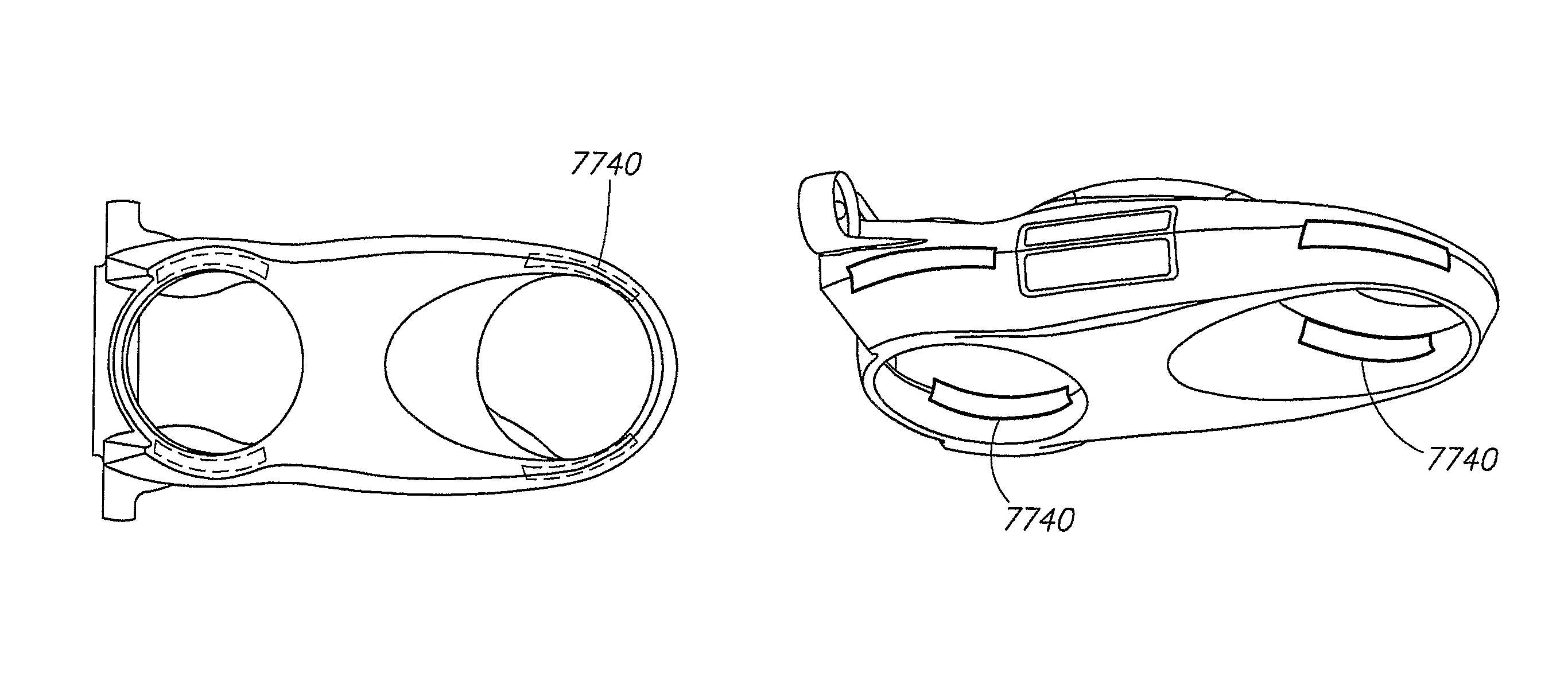
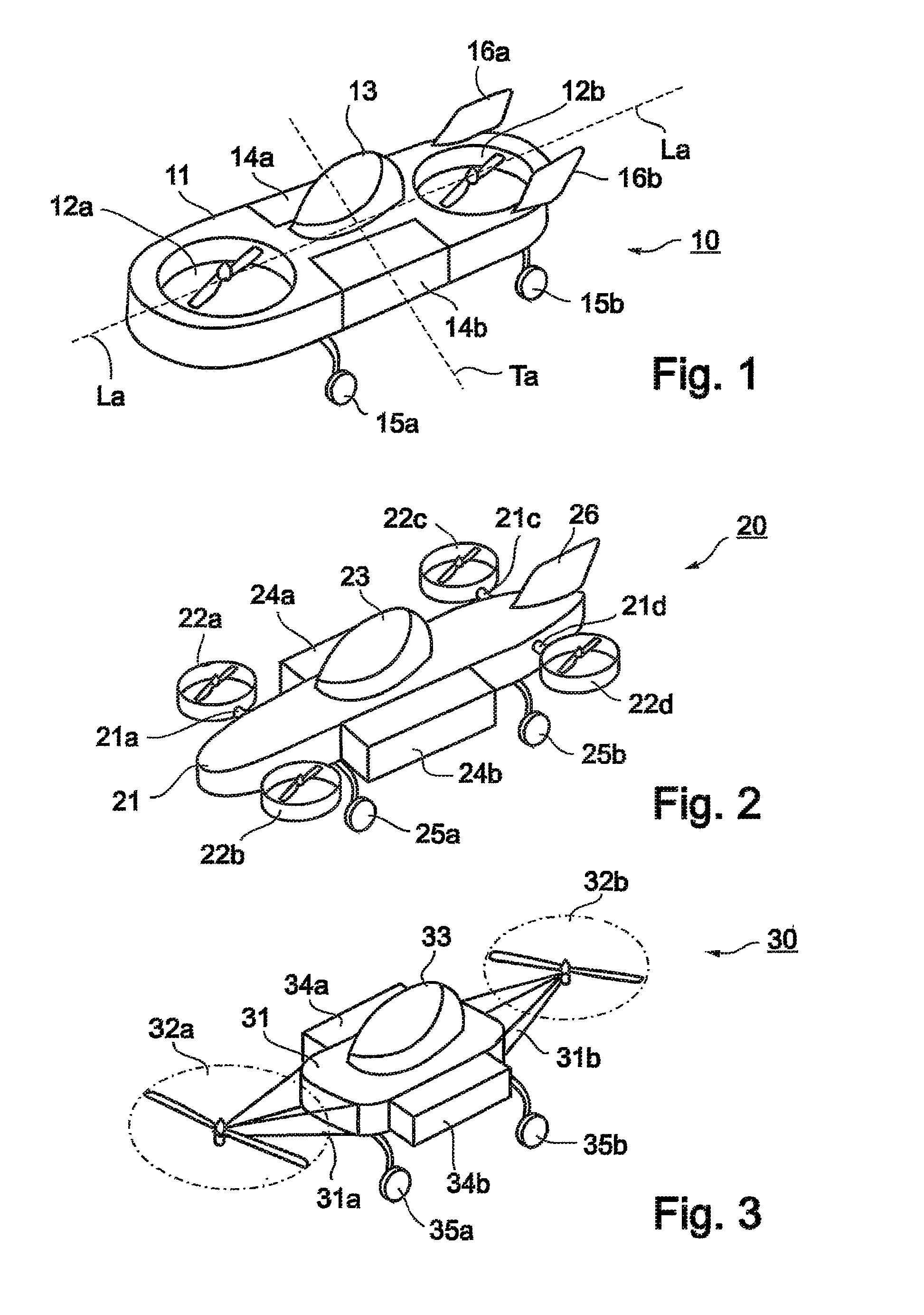
[0103]The basic construction of such a vehicle is illustrated in FIG. 1, and is therein generally designated 10. It includes a fuselage 11 having a longitudinal axis LA and a transverse axis TA. Vehicle 10 further includes two lift-producing propellers 12a, 12b carried at the opposite ends of the fuselage 11 along its longitudinal axis LA and on opposite sides of its transverse axis TA. Lift-producing propellers 12a, 12b are ducted fan propulsion units extending vertically through the fuselage and rotatable about vertical axes to propel the air downwardly and thereby to produce an upward lift.

[0104]Vehicle 10 further includes a pilot's compartment 13 formed in the fuselage 11 between the lift-producing propellers 12a, 12 and substanti...


PUM

PropertyMeasurementUnit
axes of rotationaaaaaaaaaa
anglesaaaaaaaaaa
angleaaaaaaaaaa

Abstract

Ducted air flow vehicle that includes a fuselage having a longitudinal axis, supporting at least one air flow duct and a prime mover arranged to force surrounding air into the duct through an inlet at an upper end of the duct with normally symmetrical airflow streams, thereby creating a lift force directed substantially along a duct axis; a plurality of vanes extending across the inlet, substantially parallel to the longitudinal axis; and wherein one or more groups of the vanes are selectively pivotable to align with adjacent abnormal asymmetrical airflow streams.

Description

[0001]This application is the U.S. national phase of International Application No. PCT / IL2007 / 001465 filed 27 Nov. 2007, which designated the U.S. and claims the benefit of U.S. Provisional Application No. 60 / 867,238 filed 27 Nov. 2006, the entire contents of each of which are hereby incorporated by reference.FIELD AND BACKGROUND OF THE INVENTION[0002]The present application relates to VTOL vehicles with multi-function capabilities and, specifically to ducted fan arrangements that facilitate the flow of air during hover as well as forward flight of such vehicles, and the operation and behavior of these vehicles in restrictive environments and proximity to objects.[0003]VTOL vehicles rely on direct thrust from propellers or rotors, directed downwardly, for obtaining lift necessary to support the vehicle in the air. Many different types of VTOL vehicles have been proposed where the weight of the vehicle in hover is carried directly by rotors or propellers, with the axis of rotation pe...

Claims


Application Information

Patent Timeline
Patent Type & Authority Patents(United States)
IPC IPC(8): B64C29/00
CPCB64C29/0025
Inventor YOELI, RAPHAEL
Owner URBAN AERONAUTICS
Why Eureka
Try Eureka