Dog clutch mechanism for outboard motor

a technology of outboard motors and dog clutches, which is applied in the direction of interengaging clutches, marine propulsion, and vessel construction, can solve the problems of increasing the production achieve the effects of reducing the cost of the dog clutch mechanism, reducing the surface pressure, and reducing the dimensional toleran

Inactive Publication Date: 2014-09-16
HONDA MOTOR CO LTD
View PDF16 Cites 10 Cited by
  • Summary
  • Abstract
  • Description
  • Claims
  • Application Information

AI Technical Summary

Benefits of technology

[0007]With this arrangement, when the recesses of the clutch dog member and the teeth of the forward or reverse gear are engaged together, the corner edges of the recesses are in contact with the beveled surfaces of the teeth so that there is zero clearance. In this instance because there is no clearance formed between the corner edges of the recesses and the beveled surfaces of the teeth as viewed in the rotating direction of the forward or reverse gear, the dog clutch mechanism can operate silently without generating unpleasant striking noise while the forward or reverse gear and the clutch dog member are rotating in an engaged state. The beveled surfaces of the teeth which are used in combination with the corner edges of the recesses allow for large dimensional tolerances for the recesses and the teeth, which will lead to cost reduction of the dog clutch mechanism.
[0008]In one preferred form of the invention, the corner edge is a sharp corner edge. The corner edge may be formed into a beveled corner edge in which instance the beveled corner edges reduce a surface pressure between themselves and the beveled surfaces of the teeth and thus reduce abrasive wear of the stepped bottom surfaces of the recesses and the beveled surfaces of the teeth.
[0009]Preferably, the teeth have a front surface facing in a forward direction as viewed from a rotating direction of an associated one of the forward and reverse gears, the front surface tilting forwardly at a predetermined angle with respect to an imaginary plane normal to a radial plane of the associated gear, and the recesses have a front surface engageable in face to face with the front surface of each of the teeth, the front surface of each recess tilting backwards, as viewed from the rotating direction of the forward or reverse gears, at the same angle as the predetermined angle with respect to an imaginary plane perpendicular to a radial plane of the clutch dog member. By thus tilting the front surface of each recess and the front surface of each tooth, it is possible to produce a component force acting in a direction to keep the corner edge of the recess into continuous contacting engagement with the beveled surface of the mating tooth during meshing engagement between the recess and the tooth. By the action of the component force, the clutch dog member and the forward or reverse gear are engaged together without clearance formed between the recesses and the teeth as viewed from the rotating direction of the forward or reverse gear even when the recesses and the teeth are subjected to torsional vibrations produced when the engine undergoes irregular combustion.

Problems solved by technology

Furthermore, the teeth 102 and the recesses 104 require high dimensional accuracies in terms of the dimensions in the circumferential direction, which will increase production cost the dog clutch mechanism.

Method used


Image

  • Dog clutch mechanism for outboard motor
  • Dog clutch mechanism for outboard motor
  • Dog clutch mechanism for outboard motor

Examples


Embodiment Construction

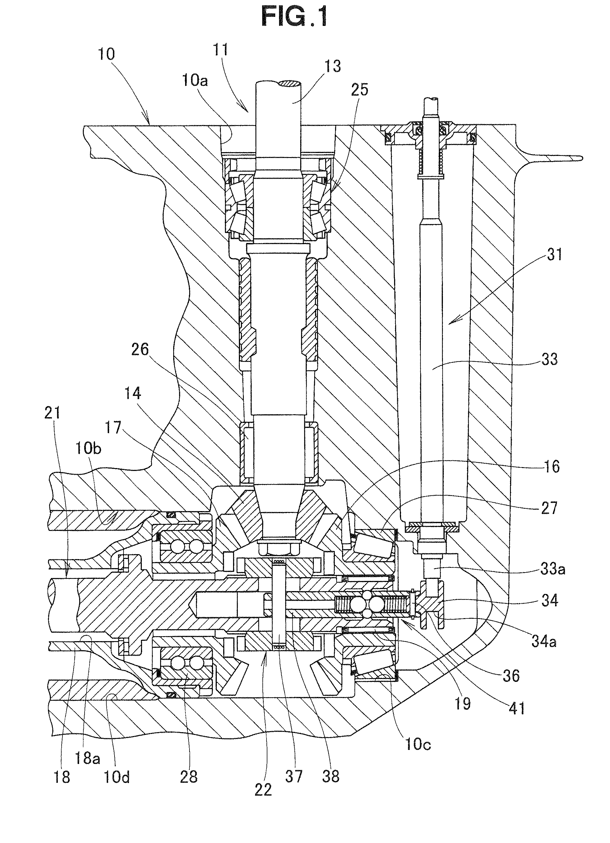
[0018]Referring now to the drawings and FIG. 1 in particular, there is shown a gear case 10 which constitutes a lower part of an outboard motor. The gear case 10 includes a power transmission mechanism 11 for transmitting power from an engine (not shown) disposed at an upper part of the outboard motor to a screw propeller (not shown) disposed at a rear end of the lower part of the outboard motor.

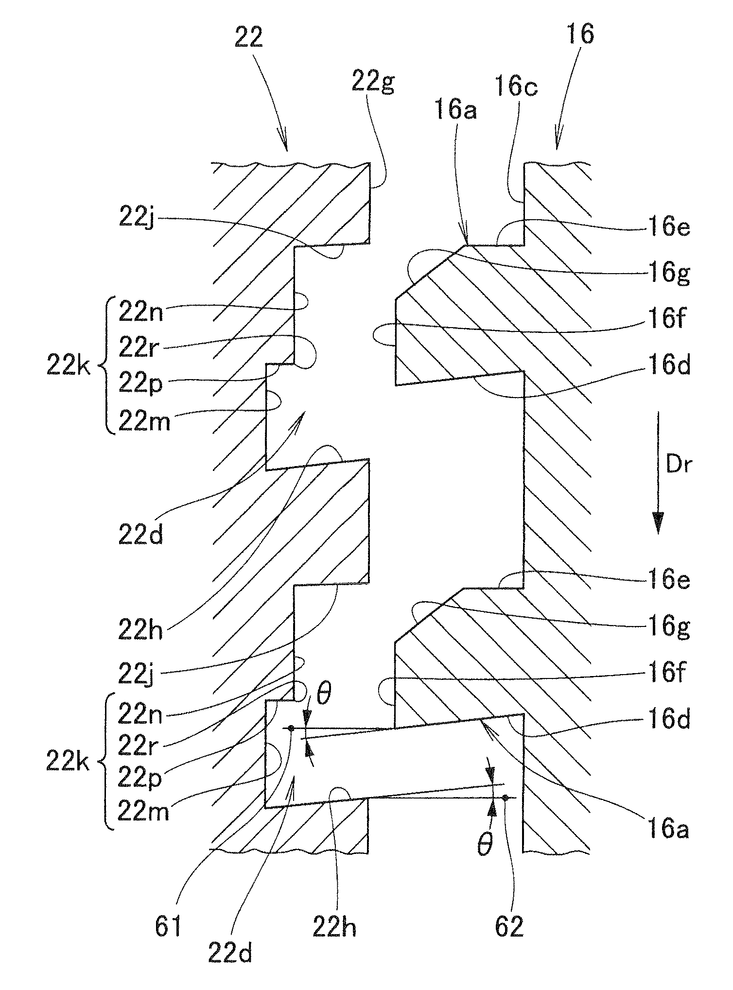
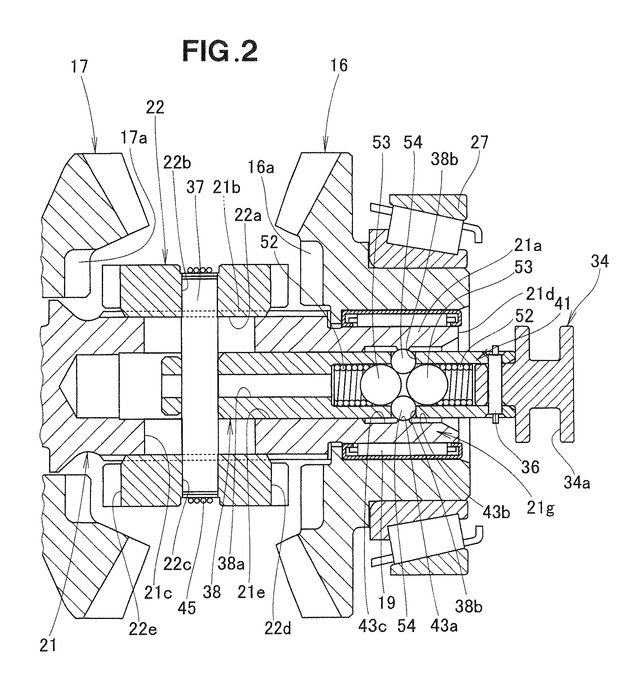
[0019]The power transmission mechanism 11 includes a drive shaft 13 extending vertically downwardly inside the gear case 10 and rotatably mounted in the gear case 10, a driving bevel gear 14 fixedly mounted to a lower end of the drive shaft 13, a pair of driven bevel gears 16 and 17 meshing with the driving bevel gear 14, a propeller shaft 21 disposed horizontally and rotatably supported by the forward driven bevel gear 16 and a propeller shaft holder 18 disposed horizontally inside the gear case 10, and a clutch dog member 22 disposed between the forward and reverse driven bevel gears 16 an...


PUM


Abstract

A dog clutch mechanism incorporated in an outboard motor includes a sliding clutch dog member splined to a propeller shaft and having recesses on each end face thereof, and a row of gear teeth formed on an end face of each of a pair of driven gears rotatably mounted on the propeller shaft. Each of the recesses has a bottom surface stepped to provide a corner edge at a stepped portion thereof. Each of the gear teeth has a beveled surface formed at a rear edge as viewed from a rotating direction of the driven gear. When the gear teeth are in mesh with the recesses of the clutch dog member, the corner edge of the stepped bottom surface of each recess is in contact with the beveled surface of the mating gear tooth.

Description

CROSS-REFERENCE TO RELATED APPLICATIONS[0001]This application is based upon and claims the benefit of priority from Japanese Patent Application No. 2009-093366, filed on Apr. 7, 2009, the entire contents of which are incorporated herein by reference.FIELD OF THE INVENTION[0002]The present invention relates to an improvement in a dog clutch mechanism for outboard motors having a sliding clutch dog splined to the propeller shaft, with recesses cut into each end face for engaging the adjacent gears.BACKGROUND OF THE INVENTION[0003]A typical example of the dog clutch mechanisms of the type concerned is disclosed in Japanese Patent Laid-open Publication (JP-A) No. 2005-48820, which corresponds to U.S. Pat. No. 6,893,305 patented on May 17, 2005. As shown in FIG. 7 hereof, the disclosed dog clutch mechanism includes a forward gear 101 rotatably mounted on a propeller shaft, not shown, the forward gear 101 having teeth 102 on a surface that opposes one end face of a clutch dog member 103. ...

Claims


Application Information

Patent Timeline
Patent Type & Authority Patents(United States)
IPC IPC(8): B63H20/20B63H23/30F16D11/10F16D11/00F16D11/14
CPCB63H20/20B63H23/30F16D11/14F16D2011/008F16D11/10
Inventor YOSHIMURA, HAJIMEOGASAWARA, RYOKATAGIRI, NOBUCHIKA
Owner HONDA MOTOR CO LTD
Why Eureka
Try Eureka