Clamping disk and cam adjusting unit

Active Publication Date: 2014-09-30
SCHAEFFLER TECH AG & CO KG
View PDF18 Cites 3 Cited by
  • Summary
  • Abstract
  • Description
  • Claims
  • Application Information

AI Technical Summary

Benefits of technology

[0029]To allow a simple testing of the mounted clamping disk for an oriented camshaft adjusting unit in an outer measurement system, the clamping disk is placed as described above with reference to the positioning mechanism advantageously with a defined a

Problems solved by technology

Here however, determining a suitable reference point for the measurement is problematic.
For example, if the inner diameter of the rotor on which the clamping disk is placed is great

Method used


Image

  • Clamping disk and cam adjusting unit
  • Clamping disk and cam adjusting unit
  • Clamping disk and cam adjusting unit

Examples


Example

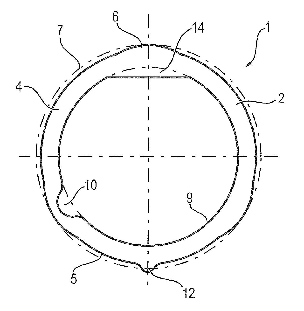
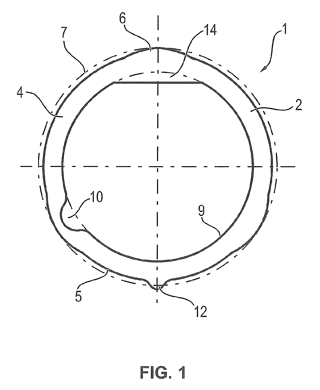
[0034]FIG. 1 shows a clamping disk 1 for a positive-fit and / or non-positive connection of a camshaft adjusting unit to a camshaft of an internal combustion engine. The clamping disk 1 has an essentially circular ring-shaped base body 2 on which a friction-increasing hard layer 4 is applied. The outer circumference of the base body 2 deviates slightly from a circular shape. A total of three notches 6 are provided at an angular distance of 120° from each other. The largest circumscribing diameter 7 of the base body 2 is given from the radial extent of the notches 6.

[0035]On the inner circumference 9 of the base body 2, the base body 2 is cut through in the axial direction by a material opening 10 approximately in the eight-o'clock position. This material opening 10 enables a distance measurement in the axial direction with respect to the contact surface of the clamping disk 10. On the outer circumference 5, the base body 2 further has a radially outward extending positioning tab 12. T...


PUM

PropertyMeasurementUnit
Diameteraaaaaaaaaa
Distanceaaaaaaaaaa
Circumferenceaaaaaaaaaa

Abstract

A clamping disk (1) for the non-positive connection of components in a cam adjusting system, a cam adjusting system (15) having a clamping disk (1) and a method for checking the mounting of the clamping disk (1) are provided. The clamping disk (1) has an essentially circular base body (2) which has at least one friction surface for a contact partner. The base body (2) is axially penetrated by a material recess (10). The mounting of the clamping disk (1) can be controlled in a simple manner by distance measuring.

Description

FIELD OF THE INVENTION[0001]The invention relates to a clamping disk for the non-positive connection of components in a camshaft adjustment system, in particular, for a non-positive connection of a camshaft adjusting unit comprising a rotor and a stator to a camshaft of an internal combustion engine. The invention also relates to a camshaft adjusting unit with such a clamping disk. In addition, the invention relates to a method for checking the installation of the clamping disk.BACKGROUND[0002]A camshaft adjustment system is used for adjusting the phase position between a camshaft and a crankshaft in an internal combustion engine. For this purpose, a rotor is typically mounted in a stator so that it can move with a rotating motion. The stator of the camshaft adjustment system is locked in rotation with the crankshaft. The rotor is locked in rotation with the camshaft. The phase position between the crankshaft and the camshaft is adjusted by means of a relative rotation of the rotor ...

Claims


Application Information

Patent Timeline
IPC IPC(8): F01L1/34F16B21/18F16B21/20
CPCF16B21/18F16B21/20Y10T403/7062Y10T29/49778
Inventor OTTERSBACH, RAINERBETZ, CHRISTOPHHERZOG, RUDIGERCHRISTEL, STEFANSEBALD, STEFANSTOLLBERGER, UWE
Owner SCHAEFFLER TECH AG & CO KG
Why Eureka
Try Eureka