Method and device for visual detection of hemolysis

a hemolysis and visual detection technology, applied in the field of visual detection devices for hemolysis, can solve the problems of affecting the accuracy and reliability of laboratory testing, false high values of these substances, and jeopardizing the well-being of individuals or groups of patients, and achieves safer and reliable test results, easy analysis, and convenient evaluation

Inactive Publication Date: 2014-09-30
HEMCHECK SWEDEN
View PDF12 Cites 7 Cited by
  • Summary
  • Abstract
  • Description
  • Claims
  • Application Information

AI Technical Summary

Benefits of technology

[0011]It is an object of the invention to provide an improved way of assessing hemolysis in immediate connection to collecting a blood sample, said assessment being possible to perform by a user e.g. in a treatment room without the necessity of a laboratory.
[0012]It is a further object of the present invention to provide a rapid way of detecting hemolysis in a whole blood sample, wherein an assessment preferably can be made within one minute, preferably within less than 30 seconds from initiating use of a device according to the invention.

Problems solved by technology

Obviously it is of great importance that all three phases are performed correctly since errors could give misleading information to the physicians and therefore jeopardize the well-being of individuals or groups of patients.
A majority of the errors seen in laboratory testing occurs in the pre analytic phase, and hemolysis is one of the most significant causes for rejection of specimen.
Hemolysis may occur either in vivo or in vitro, and is a most undesirable condition that influences the accuracy and reliability of laboratory testing.
Reasons to why hemolysis interferes with multiple biochemical analysis may be e.g. that hemoglobin interferes with the measurements (e.g. spectrophotometric methods), and also that the release of biochemical markers from the broken red blood cells causes false high values of these substances.
Obviously the above described procedures for assessing the validity of the specimen is related to a time delay causing an undesirable situation for the patient as well as leading to circuitous routines.
However the detection procedure according to WO96 / 23223 requires a series of time consuming and inefficient steps leading to a laborious procedure and undesired interruptions.

Method used


Image

  • Method and device for visual detection of hemolysis
  • Method and device for visual detection of hemolysis
  • Method and device for visual detection of hemolysis

Examples


Embodiment Construction

[0050]The foregoing aspects and many of the attendant advantages of this invention will become more readily appreciated as the same become better understood by reference to the following detailed description, when taken in conjunction with the accompanying figures. Further, the description, and the examples contained therein, are provided for the purpose of describing and illustrating certain embodiments of the invention only and are not intended to limit the scope of the invention in any way.

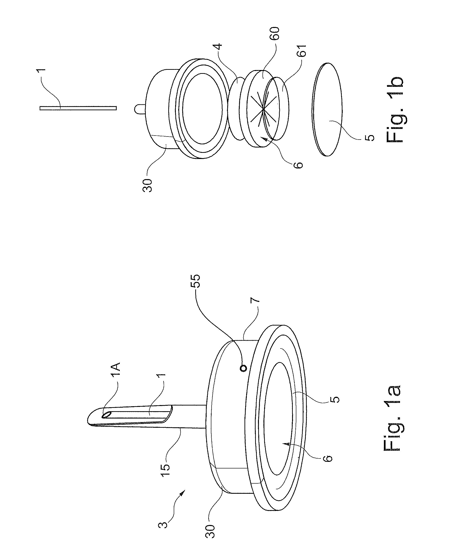
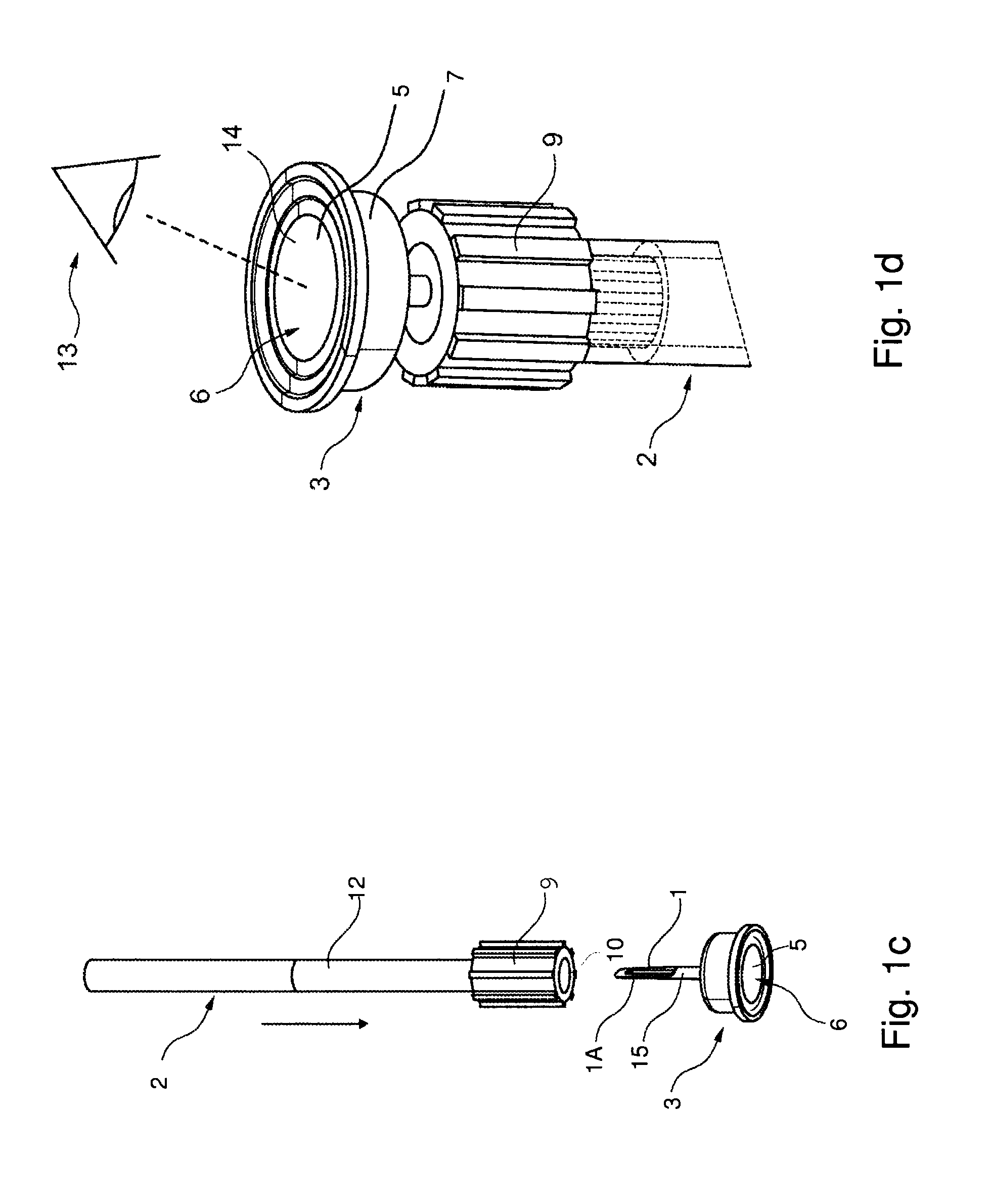
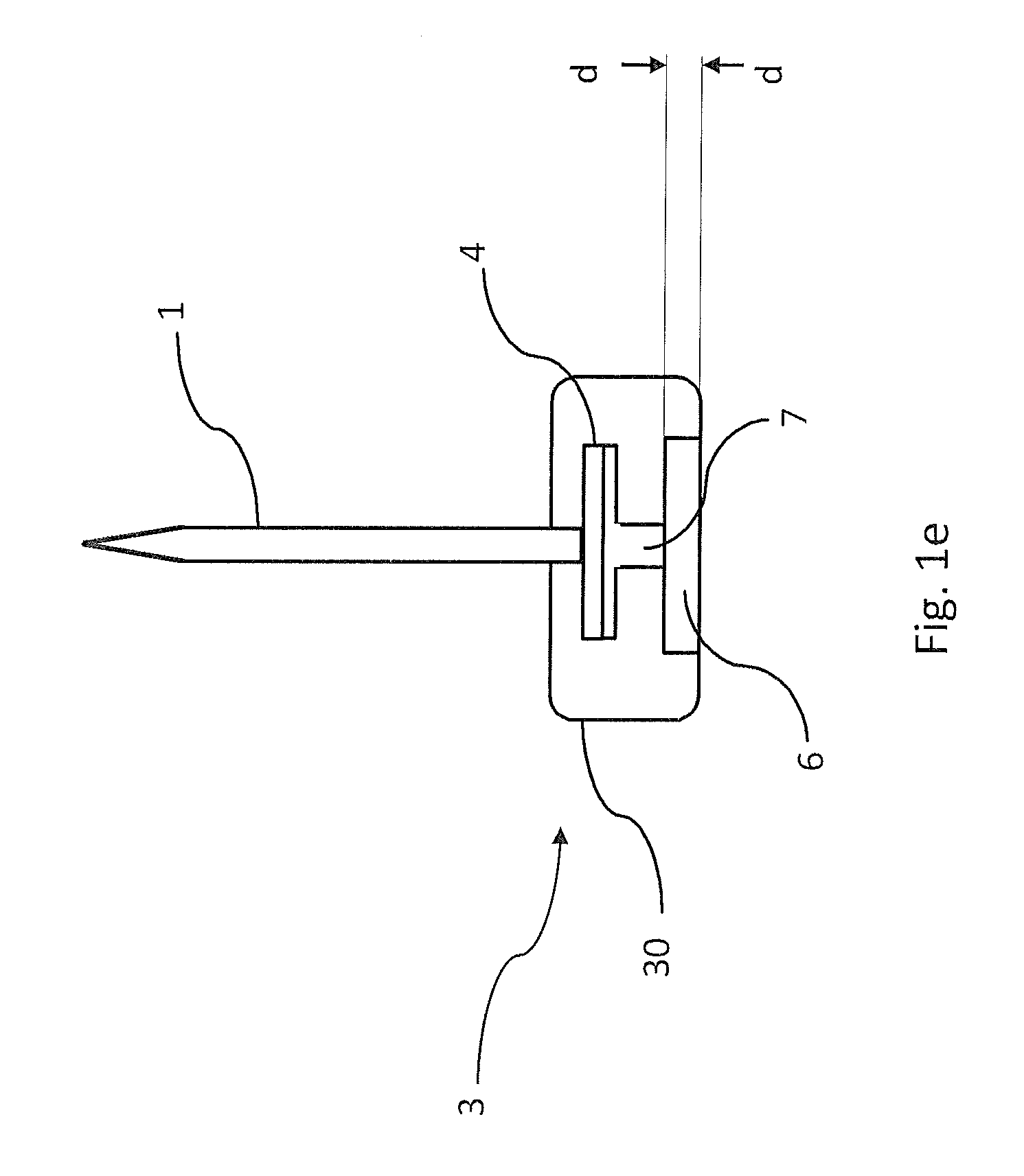
[0051]FIGS. 1a-1e show a preferred embodiment according to the invention. Herein FIGS. 1a-1b schematically illustrate a detection device 3 arranged to visually indicate hemolysis in a blood sample 12, FIG. 1a showing a perspective view of the assembled device 3 and FIG. 1b showing an exploded view of the device 3 according to FIG. 1a. FIGS. 1c-1d further show the principle for performing a quick instant testing of hemolysis of a blood sample 12 in a collection tube 2, by means of a detection de...


PUM

PropertyMeasurementUnit
concentrationaaaaaaaaaa
depthaaaaaaaaaa
volumeaaaaaaaaaa

Abstract

The present invention relates to a device for visual detection of hemolysis in a whole blood sample, comprising at least one visible detection compartment and a transfer passage connected to said visible detection compartment, said transfer passage being arranged to permit transfer of a volume of plasma from said sample to said detection compartment and wherein said transfer passage further is arranged with a separation device (4) for separating plasma from blood cells within said whole blood sample before said plasma reaches the detection compartment, wherein said device is arranged with subpressure means providing a subpressure inside said detection compartment for generating a force urging said volume of plasma to be transferred from said whole blood sample to said detection compartment through said transfer passage and via said separation device.

Description

TECHNICAL FIELD[0001]The following invention relates to a device for visual detection of hemolysis in a whole blood sample, comprising a visible detection compartment and a transfer passage connected to said visible detection compartment, said transfer passage being arranged to permit transfer of a volume of plasma from said sample to said detection compartment and wherein said transfer passage further is arranged with a separation device for separating plasma from blood cells within said whole blood sample before said plasma reaches the detection compartment. The invention also relates to a method for visual detection of hemolysis in a whole blood sample.BACKGROUND ART[0002]Laboratory testing is probably the most common clinical routine performed in modern medical care. Cerebral spinal fluid and urine may be used forbiochemical analysis, however blood is the body fluid mostly used and these tests are highly important diagnostic and prognostic tools in the everyday patient care.[000...

Claims


Application Information

Patent Timeline
Patent Type & Authority Patents(United States)
IPC IPC(8): A61M1/00G01N33/49
CPCA61M1/00G01N33/491A61M2205/3306A61B5/1438A61B5/15003A61B5/150351A61B5/150389A61B5/150473A61B5/150755A61B5/153A61B5/154A61B5/157G01N21/78A61B5/150213A61B5/150251
Inventor KARLSSON, MATHIAS
Owner HEMCHECK SWEDEN
Why Eureka
Try Eureka