
Heating unit of vehicle heating system

a vehicle heating and heating unit technology, applied in the direction of ventilation systems, heating types, lighting and heating apparatus, etc., can solve the problems of reducing reducing the rate of electric power consumption, and reducing the efficiency of power consumption, so as to reduce the rate of heating power consumption and reduce the cruising distance of the vehicle. , the effect of prolonging the battery charging cycle and increasing the running distance of the vehicl

Active Publication Date: 2014-09-30
TENMA +1
View PDF28 Cites 3 Cited by
  • Summary
  • Abstract
  • Description
  • Claims
  • Application Information

AI Technical Summary

Benefits of technology

This invention can make it more efficient to heat up a car, which means it can drive farther distances on battery power. This also means the car's battery lasts longer in between charges.

Problems solved by technology

Then, electric power is consumed at a high rate to give rise to a problem of a short cruising distance.
However, the vehicle weight will be raised accordingly to by turn lower the power consumption efficiency and reduce the cruising distance of the vehicle.
A PTC heater is a heater having a characteristic that its power consumption rate is reduced as its temperature rises but it is accompanied by a problem of consuming power at a high rate in a situation where the air conditioning temperature of the vehicle in which it is mounted and hence the temperature of the PTC heater itself is not high.
Particularly, when such a PTC heater is mounted in an electric vehicle, all the energy for driving the vehicle to run depends on one or more batteries so that, as the power consumption rate of the vehicle air conditioning system rises, the running distance of the vehicle is reduced and hence the battery charging cycle of the vehicle becomes short.

Method used


Image

  • Heating unit of vehicle heating system
  • Heating unit of vehicle heating system
  • Heating unit of vehicle heating system

Examples


embodiment 1

[0025]Now, an embodiment of vehicle heating system according to the present invention that is arranged in an air conditioning unit will be described below by referring to the related drawings.

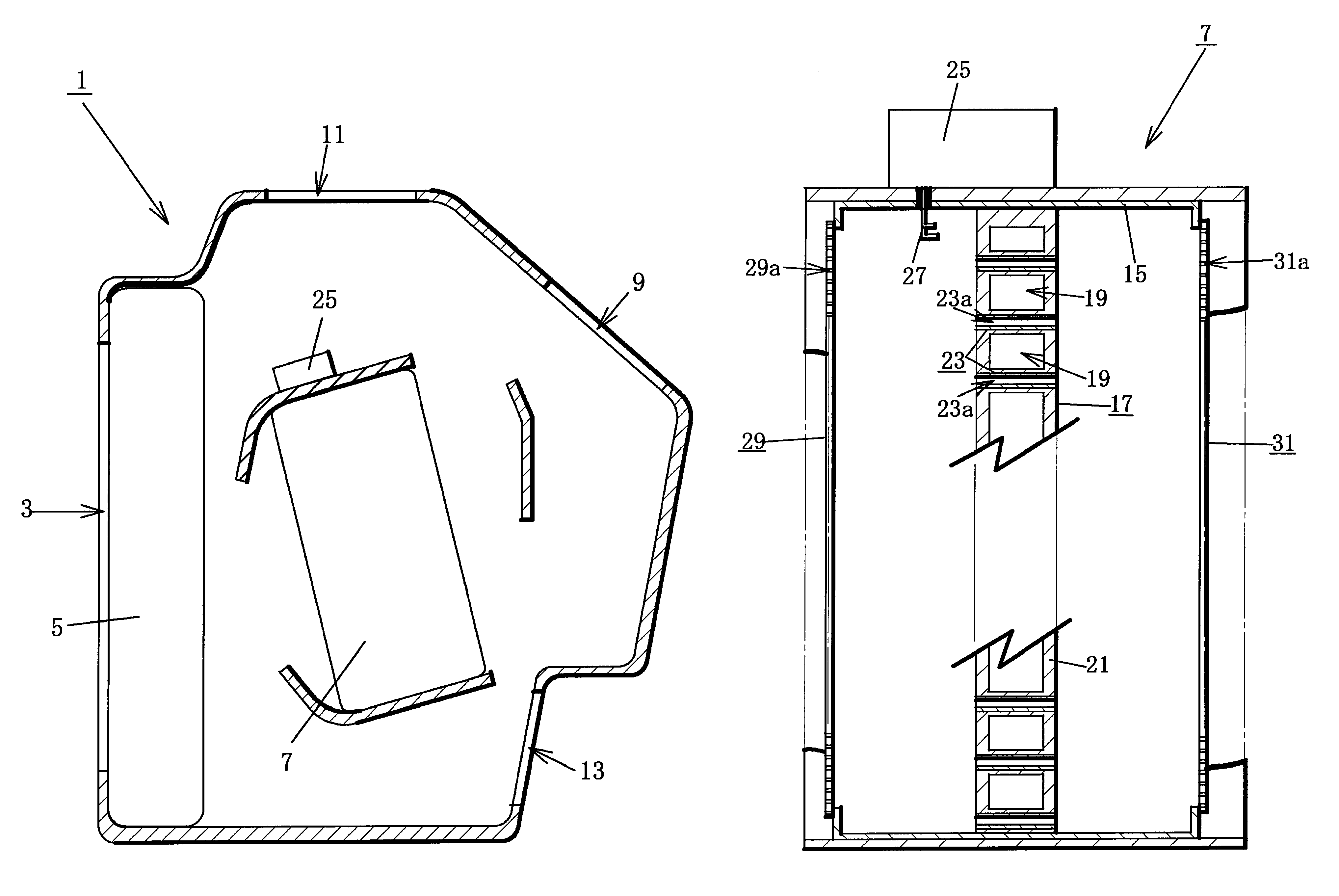
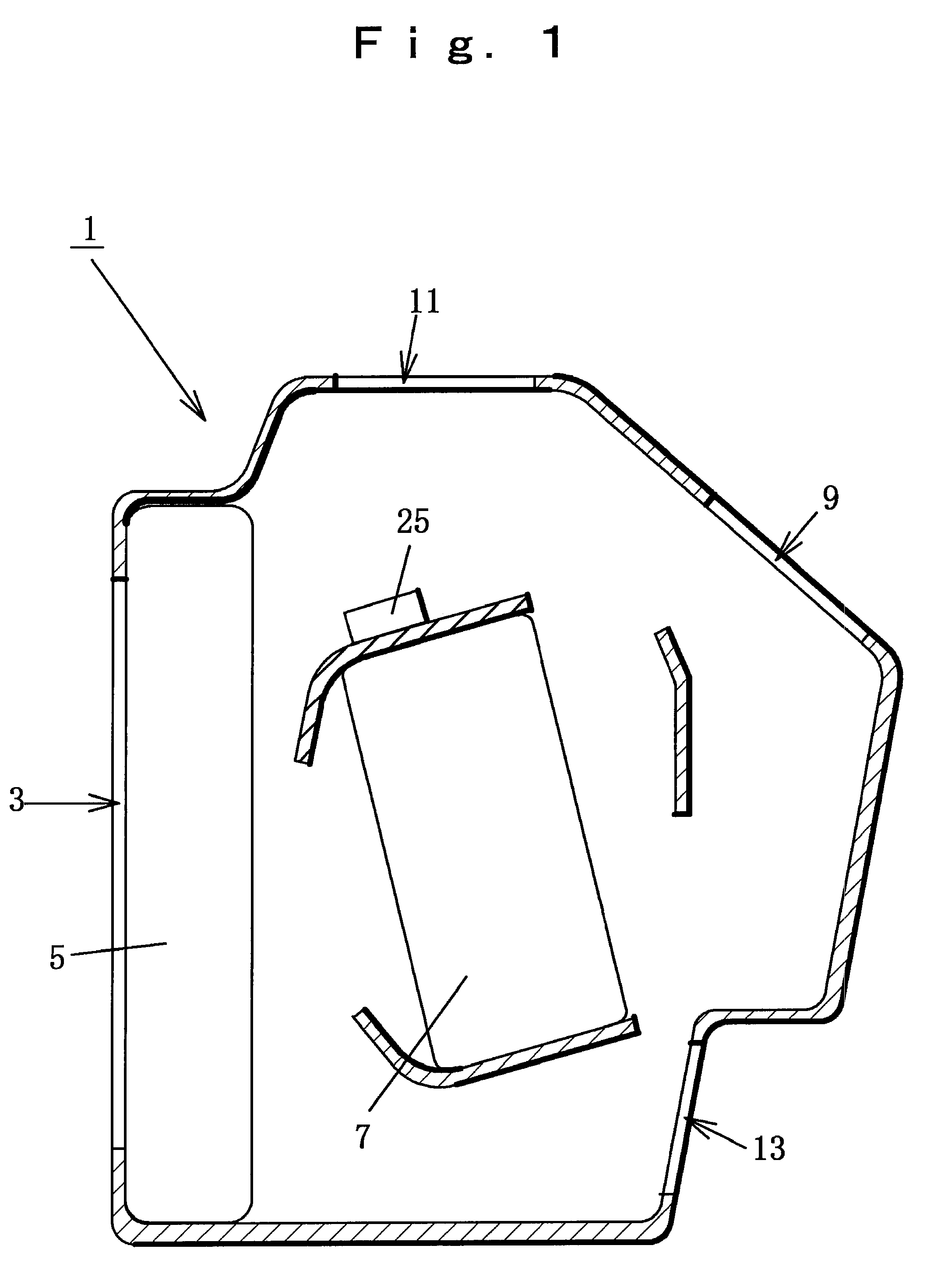
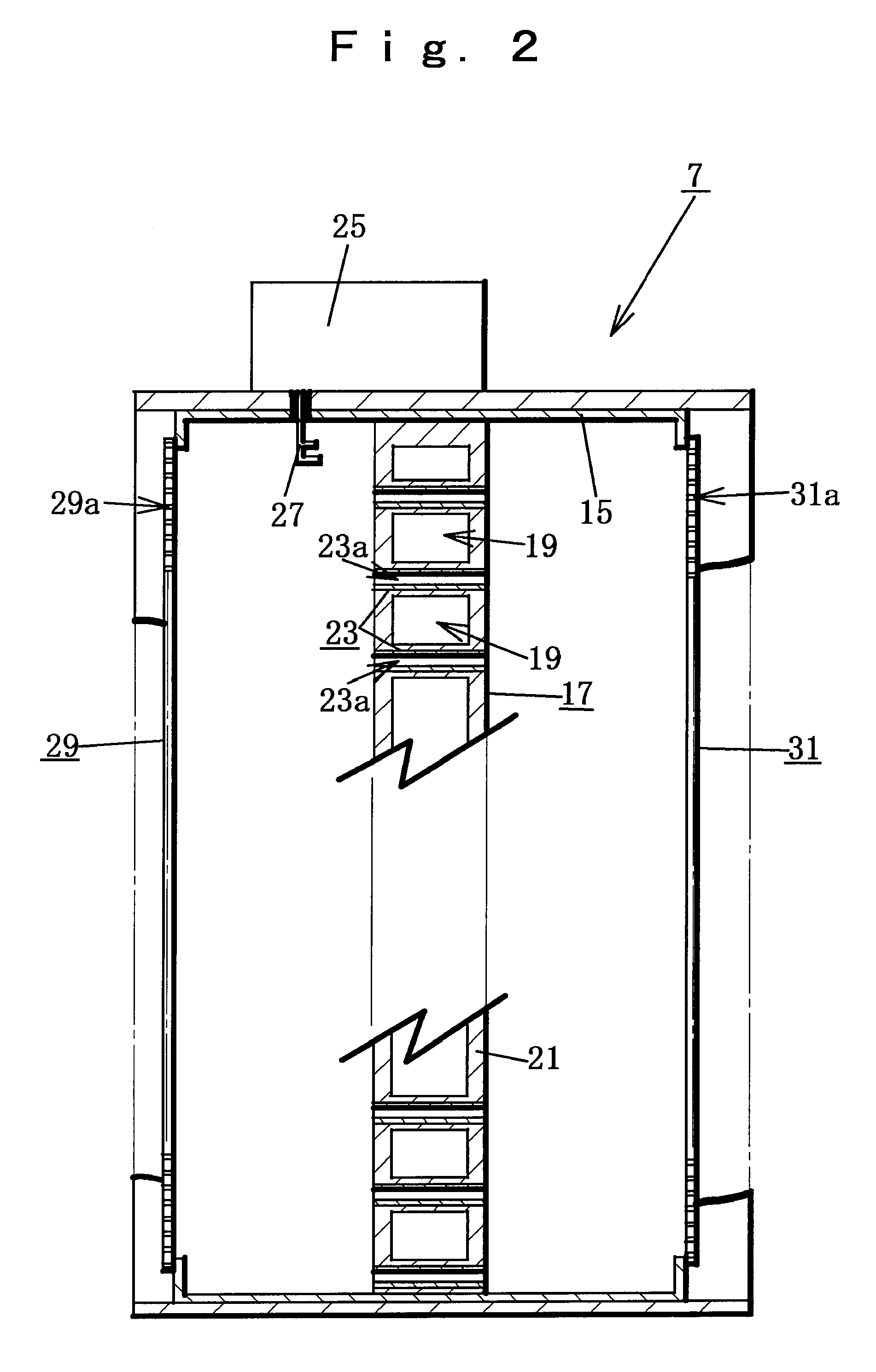
[0026]FIGS. 1 through 3 schematically illustrate the first embodiment of the present invention that is an exemplar vehicle air conditioning system for hybrid vehicles. Air conditioning unit 1 of the air conditioning system is arranged below an instrument panel in a vehicle and blown air that is at least internal air or external air taken in by way of an internal air / external air switching door (which blown air may be a mixture of internal air and external air) as a blower fan (not shown) is driven to rotate is blown into the air conditioning unit 1 by way of an air intake port 3. The air blown into the air conditioning unit 1 is cooled as it passes an evaporator 5 and subsequently passes and / or bypasses heating unit 7 of the vehicle heating system at a ratio corresponding to the degree of openi...

embodiment 2

[0045]FIGS. 5 and 6 illustrate an embodiment of vehicle air conditioning system that is suitable for an electric vehicle or a hybrid vehicle provided with an air-cooled engine. Since this embodiment is the same as Embodiment 1 except that the heater core 53 of the heating unit 51 of this embodiment has a configuration as described below, the components that are same as those of Embodiment 1 are denoted by the same reference symbols and will not be described further in detail.

[0046]The heater core 53 is arranged in the casing 15 of the heating unit 51 orthogonally relative to the air blowing direction at a middle section of the inside of the casing 15 as viewed in the air blowing direction. The support 55 of the heater core 53 is formed by using a plate-shaped member that is made of a magnetically permeable ceramics material or a heat-resistant synthetic resin material and large enough for shutting away the space in the casing 15. A large number of pipe-shaped microwave absorbing / hea...


PUM


Abstract

A heating unit can reduce the rate of power consumption for heating a vehicle, so that the running distance of the vehicle is increased and hence the battery charging cycle of the vehicle is prolonged. A heating unit of a vehicle heating system includes a casing made of a metal material capable of electromagnetically shielding microwaves, a support arranged in the hollow section of the casing, a plurality of microwave absorbing / heat emitting members arranged at the support and a microwave outputting unit arranged in the casing to output microwaves toward respective microwave absorbing / heat emitting members, blown air being heated by heat generated as a result of absorption of microwaves by the microwave absorbing / heat emitting members at the time for blown air to flow from the upstream side to the downstream side in the hollow sections of the microwave absorbing / heat emitting members.

Description

BACKGROUND OF THE INVENTION[0001]1. Field of the Invention[0002]The present invention relates to a heating unit of a vehicle heating system. More particularly, the present invention relates to a heating unit for heating blowing air at a low power consumption rate by arranging microwave absorbing / heat emitting members that absorb microwaves and emit heat in a vehicle air conditioning unit or in a vehicle air duct.[0003]2. Prior Art[0004]Various hybrid vehicles and electric vehicles have been proposed and developed for the purpose of improving the fuel efficiency of vehicles and reducing the quantity of CO2 gas emissions from vehicles in recent years. Such vehicles, electric vehicles in particular, are equipped with an electric motor that is operated by electric power supplied from the battery mounted in the vehicle when driving the vehicle by means of the electric motor. Then, electric power is consumed at a high rate to give rise to a problem of a short cruising distance. The cruisi...

Claims


Application Information

Patent Timeline
Patent Type & Authority Patents(United States)
IPC IPC(8): H05B6/80F24D5/00F24F7/00B61D27/00B60H1/00B60H1/02B60H1/03H05B6/66H05B6/50H05B6/70H05B6/64
CPCH05B6/802Y10T137/6606
Inventor NIWA, NORIONODA, RYOUSEIANZAI, HIROKI
Owner TENMA
Learn More