Apparatus for shearing and breaking nonferrous casting

a technology of nonferrous castings and apparatuses, which is applied in the field of apparatuses for shearing and breaking, mainly, nonferrous castings, can solve problems such as the problem of improving the patent document 1, achieve the effects of improving the inputability of crushed materials, reducing the temperature drop of molten metal, and improving the conveying performance of sheared and broken materials

Active Publication Date: 2014-10-07
YUATSUKI
View PDF14 Cites 3 Cited by
  • Summary
  • Abstract
  • Description
  • Claims
  • Application Information

AI Technical Summary

Benefits of technology

[0038]According to the invention, materials to be crushed are finely sheared and broken by at least the intermediate cutter unit and the lower cutter unit. As a result, the conveying performance of sheared and broken materials is improved. Also, size reduction of crushed materials to be crushed improves the inputability of crushed materials into a melting furnace and their meltability and reduces a drop in temperature of molten metal. Further, size reduction of crushed materials makes a water pooling portion smaller, resulting in occurrence of less phreatic explosion.
[0039]Thus, an apparatus for shearing and breaking nonferrous castings which are materials to be crushed, comprises one cutting tool provided in a frame which is composed of two side plates and a bridging plate; the other cutting tool being opposed to the one cutting tool and being pivotally attached via a supporting shaft disposed to the frame; movable means for shearing and breaking which moves the other cutting tool; an input opening for nonferrous castings which are materials to be crushed, the input opening being formed between the upper parts of the one cutting tool and the other cutting tool; and a discharge opening having a converging shape and being formed between the lower parts of the one cutting tool and the other cutting tool, wherein the one cutting tool includes one base plate and one cutter unit disposed on the one base plate, and the other cutting tool includes the other base plate and the other cutter unit disposed on the other base plate,
[0040]each of the one cutter unit and the other cutter unit is a cutter unit comprised of at least an intermediate cutter unit located on an intermediate stage and a lower cutter unit located on a lower stage,
[0041]the intermediate cutter units of the one cutter unit and the other cutter unit have a substantially same shape, both of the cutter units being engaged with a gap formed therebetween to provide a shearing cutter unit, and each of the cutter units being a multi-vertex cutter part formed into a multi-vertex shape by a plurality of rhombic cutting edges combined and crucial cutting edges connected to respective intersections of diagonals of the rhombic cutting edges,
[0042]the lower cutter units of the one cutter unit and the other cutter unit includes a concave cutting edge and a convex cutting edge, respectively, and
[0043]the concave cutting edge and the convex cutting edge are engaged with a gap formed therebetween.

Problems solved by technology

However, Patent Document 1 has a problem to be improved.

Method used


Image

  • Apparatus for shearing and breaking nonferrous casting
  • Apparatus for shearing and breaking nonferrous casting
  • Apparatus for shearing and breaking nonferrous casting

Examples


Embodiment Construction

[0083]One embodiment of the present invention will be described.

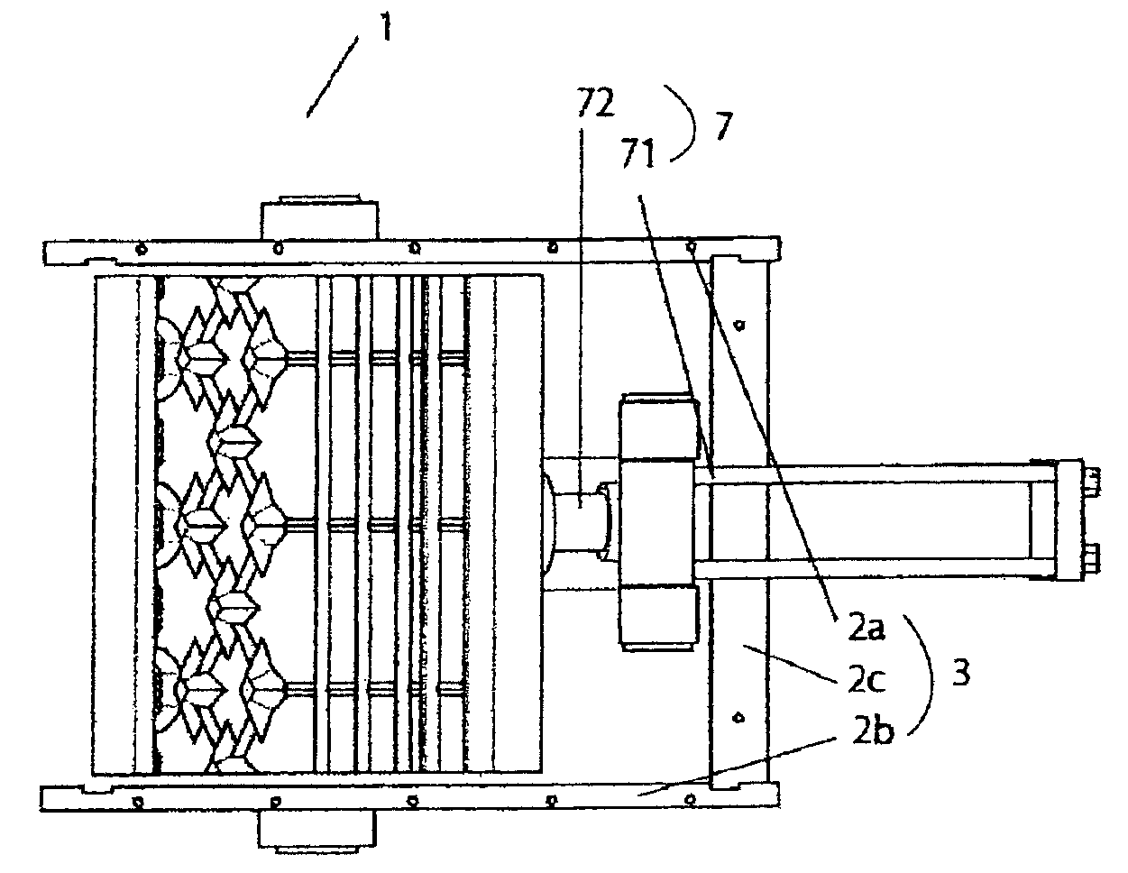
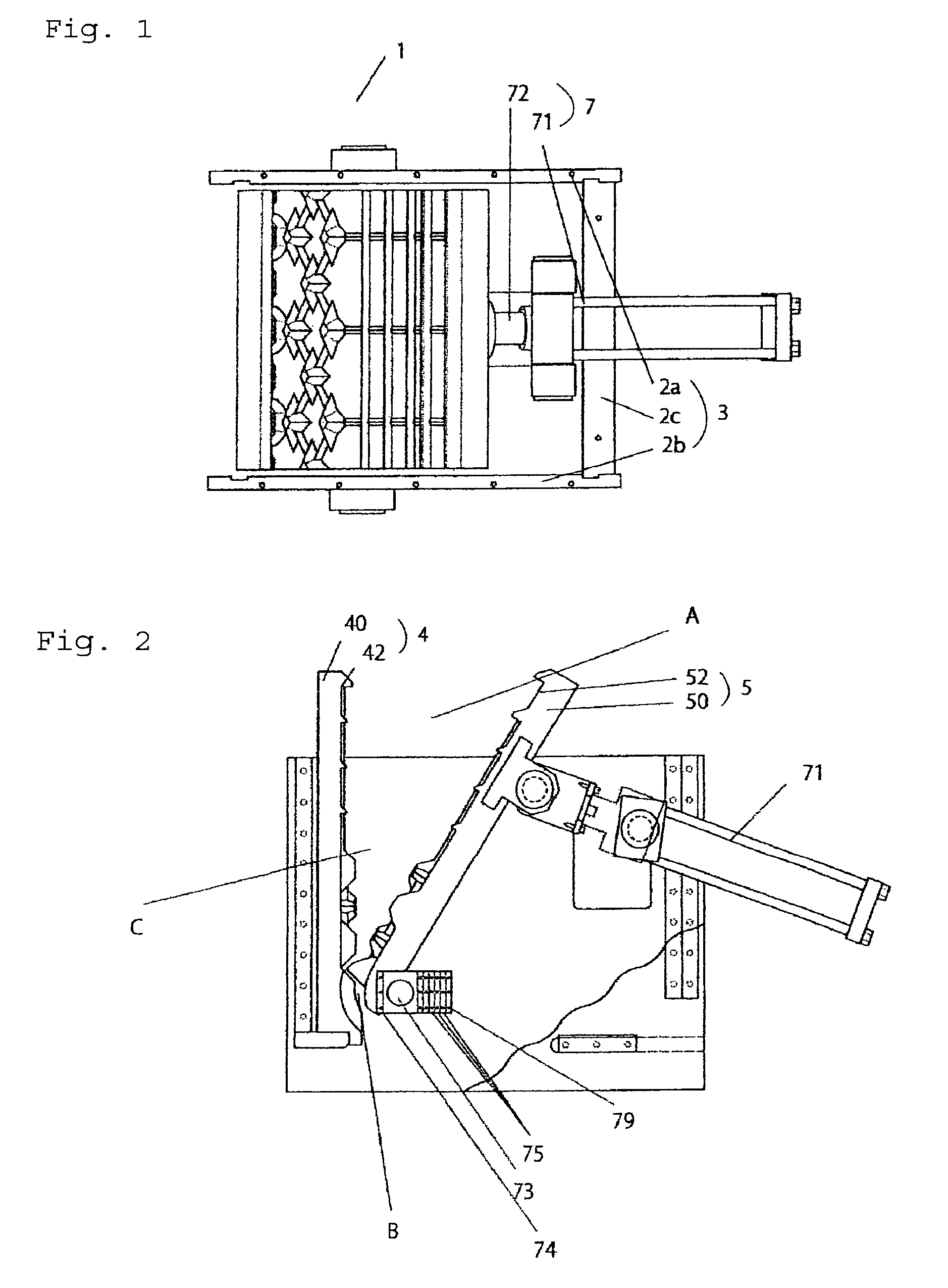
[0084]Hereinafter, one embodiment of the shearing and breaking apparatus for nonferrous castings 1 of the present invention will be described with reference to the accompanying drawings. As shown in FIG. 1, the shearing and breaking apparatus for nonferrous castings 1 includes, as major components, a frame 3 which is composed of side plates 2a, 2b and a bridging plate 2c and is open at the top and bottom thereof, one cutting tool 4 disposed to the frame 3, the other cutting tool 5 opposed to the one cutting tool 4 and pivotally attached via a supporting shaft disposed to the frame and movable means 7 which moves the other cutting tool 5 forward and backward. An input opening A is formed between the upper parts of the one cutting tool 4 and the other cutting tool 5, and a discharge opening B having a converging shape is formed between the lower parts of the one cutting tool 4 and the other cutting tool 5. As shown in FIG...


PUM


Abstract

An apparatus for shearing and breaking nonferrous castings of the present invention includes a first cutter unit and a second cutter unit disposed in a frame. Each of the first cutter unit and the second cutter unit includes at least an intermediate cutter unit located at the intermediate stage and a lower cutter unit located at the lower stage. Each of the intermediate cutter units is a multi-vertex cutter part formed into a multi-vertex shape by rhombic cutting edges and crucial cutting edges connected to the respective intersections of diagonals of the rhombic cutting edges. The lower cutter units respectively have a concave cutting edge and a convex cutting edge which are engaged with a gap being formed therebetween.

Description

TECHNICAL FIELD[0001]The present invention relates to an apparatus for shearing and breaking, mainly, nonferrous castings such as aluminum castings, which has a space for crushing defined between one cutter unit and the other cutter unit and pinches and presses to crush materials placed in the space by the one cutter unit and the other cutter unit.BACKGROUND ART[0002]As an apparatus for shearing aluminum, there is disclosed Japanese Patent Application Laid-Open No. 2005-87915 “Aluminum shearing apparatus”, as Patent Document 1. Patent Document 1 discloses a shearing apparatus especially for shearing aluminum, using half-cut pyramid-shaped cutting edges each having a special cutting tooth shape. According to the description, the aluminum shearing apparatus includes one cutter unit and the other cutter unit facing each other, which are pivotally attached to a frame and have half-cut pyramid-shaped cutting edges disposed in a zigzag manner, movable means for shearing which moves the ot...

Claims


Application Information

Patent Timeline
Patent Type & Authority Patents(United States)
IPC IPC(8): B02C19/00B02C17/04B02C1/04B02C1/10
CPCB02C1/04B02C1/043B02C1/10
Inventor OKUYA, YASUAKI
Owner YUATSUKI
Why Eureka
Try Eureka