Liquid ejection apparatus

a technology of liquid ejection and pump, which is applied in the direction of printing and inking apparatus, etc., can solve the problems of insufficient damper removal and large pressure variation, and achieve the effect of efficient liquid supply, effective elimination of pulsating action of pumps, and accurate control

Active Publication Date: 2014-10-07
FUJIFILM CORP
View PDF15 Cites 17 Cited by
  • Summary
  • Abstract
  • Description
  • Claims
  • Application Information

AI Technical Summary

Benefits of technology

[0008]There are two main approaches to reducing pressure variation in the supplied liquid. One approach is to use dampers, as described in Japanese Patent Application Publication No. 2009-101516. The other approach is to shorten the length of a tube for conveying the liquid to the head and / or to increase the internal diameter of the tube.

Problems solved by technology

Viewed from this perspective, when a liquid ejection apparatus having line heads is considered, since a large amount of liquid is ejected, if an inappropriate layout of flow channels of the liquid is selected (for instance, if the flow channels are made too long), then there is a concern that the pressure variation will become so large that it cannot be sufficiently eliminated with dampers.

Method used


Image

  • Liquid ejection apparatus
  • Liquid ejection apparatus
  • Liquid ejection apparatus

Examples


first embodiment

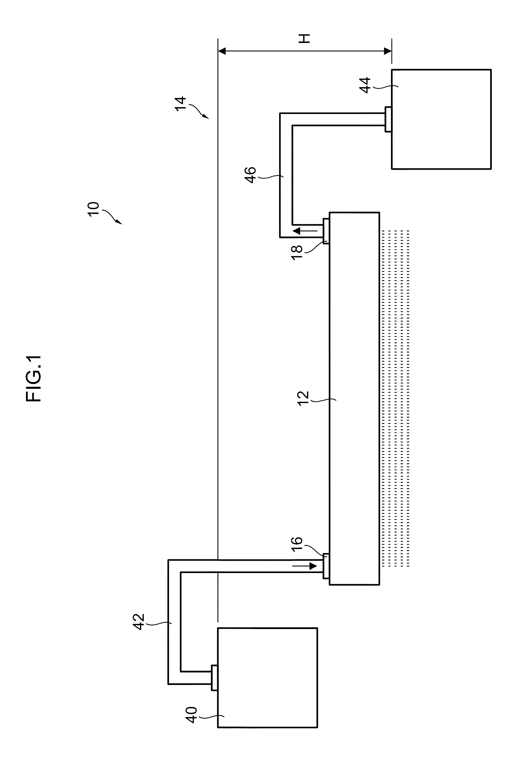
[0070]FIG. 1 is a schematic drawing of a liquid ejection apparatus 10 according to a first embodiment of the present invention.

[0071]As shown in FIG. 1, the liquid ejection apparatus 10 includes a liquid ejection head 12 (hereinafter referred simply as the “head”12) configured to eject droplets of liquid, and a liquid supply and recovery unit 14 configured to supply and recovery the liquid to and from the head 12.

[0072]

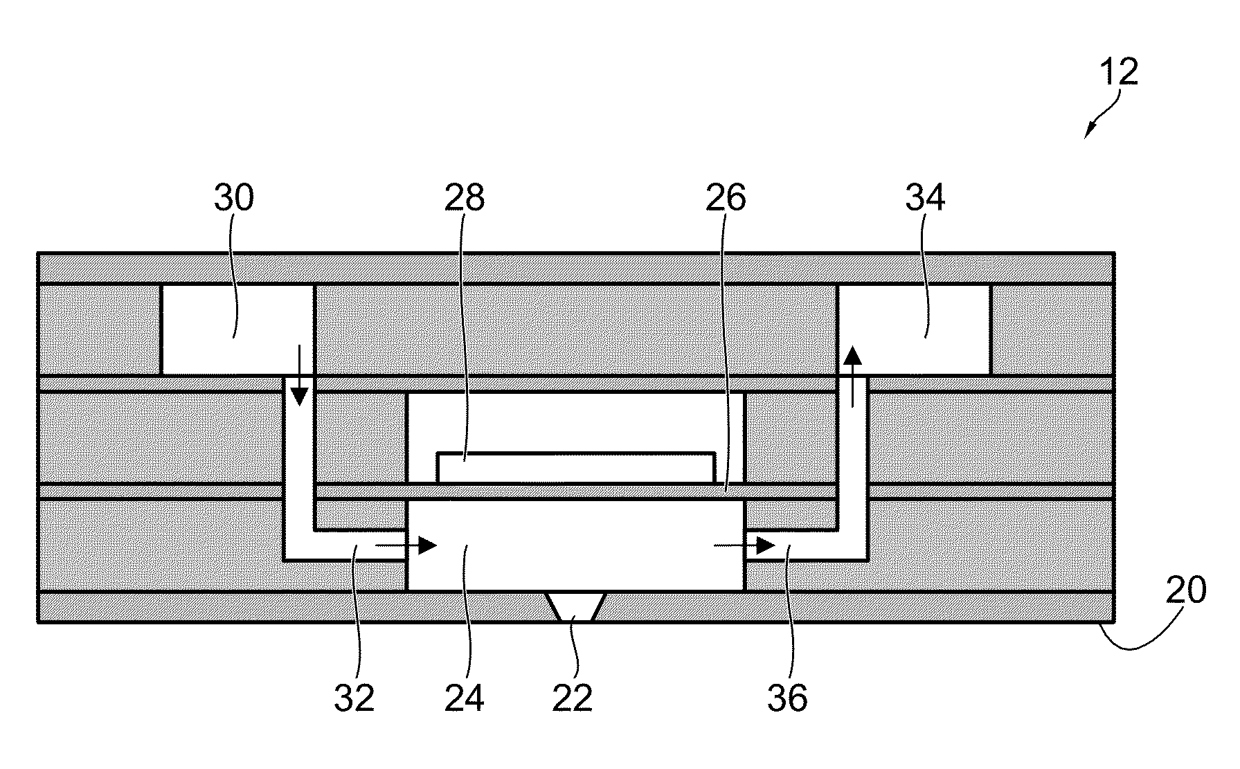
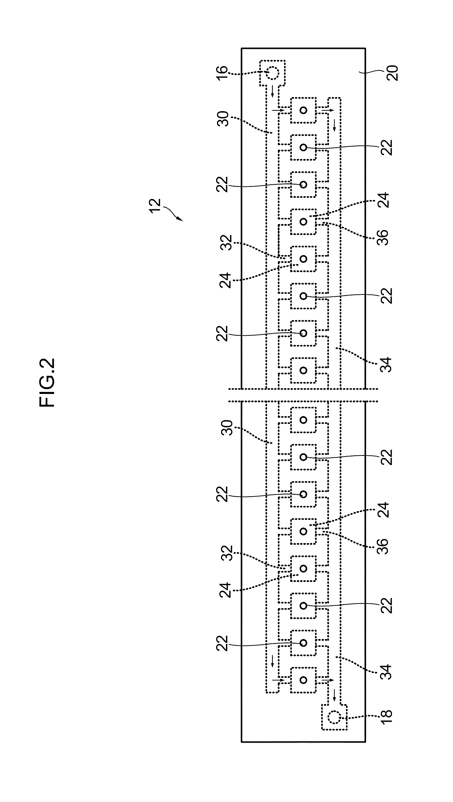
[0073]The head 12 is a so-called circulation head, which is provided with a supply port 16 and a recovery port 18 for the liquid. The liquid is continuously supplied to the head 12 though the supply port 16 and is continuously recovered from the head 12 through the recovery port 18. Consequently, a flow of the liquid from the support port 16 toward the recovery port 18 is formed inside the head 12, and it is thereby possible to prevent the liquid inside the head 12 from keeping bubbles or increasing in the viscosity.

[0074]The head 12 is formed in a rectangular block s...

second embodiment

[0130]FIG. 5 is a schematic drawing of a liquid ejection apparatus 10A according to a second embodiment of the present invention.

[0131]As shown in FIG. 5, the liquid ejection apparatus 10A according to the present embodiment carries out the supply and recovery of the liquid by means of pumps. The composition of the head 12 is the same as the liquid ejection apparatus 10 according to the first embodiment described above, and therefore only the composition of the liquid supply and recovery unit 14 for carrying out the supply and recovery of the liquid to and from the head 12 is described here.

[0132]

[0133]As shown in FIG. 5, the liquid supply and recovery unit 14 includes: a supply tank 40; a supply tube 42; a recovery tank 44; a recovery tube 46; a supply pump 48, which conveys the liquid contained in the supply tank 40 to the head 12 through the supply tube 42; a supply damper 50, which is arranged in the supply tube 42; a recovery pump 52, which conveys the liquid from the head 12 t...

third embodiment

[0154]FIG. 6 is a schematic drawing of a liquid ejection apparatus 100 according to a third embodiment of the present invention.

[0155]As shown in FIG. 6, in the liquid ejection apparatus 100 according to the present embodiment, a liquid ejection head 112h is constituted by joining together a plurality of head modules 112m. The liquid is independently supplied to and recovered from each head module 112m, by the liquid supply and recovery unit 114.

[0156]

[0157]As described above, the head 112h according to the present embodiment is constituted by joining together the plurality of head modules 112m.

[0158]The head modules 112m have the same structure. Furthermore, the basic structure of each head module 112m is the same as the head 12 according to the first embodiment described above. More specifically, each of the head modules 112m is provided with a supply port 116 and a recovery port 118, and the liquid is supplied continuously to the supply port 116 and is also recovered continuousl...


PUM


Abstract

A liquid ejection apparatus includes: a head including: a nozzle configured to eject liquid; a supply port to which the liquid is continuously supplied; and a recovery port from which the liquid is continuously recovered; a supply flow channel through which the liquid is supplied to the head; and a recovery flow channel through which the liquid is recovered from the head. A flow channel resistance inside the head from the supply port to the nozzle is R_HEAD_IN. A flow channel resistance inside the head from the nozzle to the recovery port is R_HEAD_OUT. A flow channel resistance of the supply flow channel is R_CHANNEL_IN. A flow channel resistance of the recovery flow channel is R_CHANNEL_OUT. The supply and recovery flow channels are laid out so as to satisfy a condition of R_CHANNEL_IN>R_CHANNEL_OUT when R_HEAD_IN>R_HEAD_OUT, or a condition of R_CHANNEL_IN<R_CHANNEL_OUT when R_HEAD_IN<R_HEAD_OUT.

Description

BACKGROUND OF THE INVENTION[0001]1. Field of the Invention[0002]The present invention relates to a liquid ejection apparatus, and more particularly to technology which optimizes a layout of flow channels in a liquid ejection apparatus in which liquid to be ejected from nozzles of a liquid ejection head is supplied to the liquid ejection head while circulated through the liquid ejection head.[0003]2. Description of the Related Art[0004]A liquid ejection head (e.g., an inkjet head, hereinafter referred simply to as the “head”) configured to eject liquid (e.g., droplets of ink) has a problem in that ejection defects occur if the liquid inside the head contains bubbles or has the viscosity increased. In order to prevent such ejection defects caused by bubbles in the liquid inside the head or the increased viscosity of the liquid inside the head, it is known technology to supply the liquid to the head while circulating the liquid through the head.[0005]In cases of supplying the liquid to...

Claims


Application Information

Patent Timeline
Patent Type & Authority Patents(United States)
IPC IPC(8): B41J2/175B41J2/14B41J2/18
CPCB41J2/175B41J2/18B41J2/14233B41J2202/11B41J2202/12B41J2002/14241B41J2002/14419
Inventor ARIMOTO, MAKOTO
Owner FUJIFILM CORP
Why Eureka
Try Eureka