Injection molding method including machining of both injection mold and molded product

Active Publication Date: 2014-10-07
DEPUY SYNTHES PROD INC
View PDF9 Cites 0 Cited by
  • Summary
  • Abstract
  • Description
  • Claims
  • Application Information

AI Technical Summary

Benefits of technology

[0006]The method according to the exemplary embodiment of the present invention may speed production of individual products (e.g., implants) with the injection molding technique and may further permit an injection mold to be quickly produced for an individual product without the need for a pattern of the product to be molded. The method according to the invention may also allow the molded product to be machined (e.g. by milling) without the need for further holding, gripping or fixation devices and will make a two part mold unnecessary due to the configuration of the injection mold as a lost mold. Furthermore, injection and coolant ducts can be individually configured and the mold may be mounted on an interface plate suitable as a base for different machines.
[0020]In another exemplary method, the production of the injection mold may include the production of one or more feeder ducts so that the injection mold can be completely finished via layer-by-layer deposition without requiring subsequent processing or machining.

Problems solved by technology

One problem associated with known injection molds is that usually a two part mold is configured in such a way that a product formed in the mold is not held in either part of the two part mold so that the product must be fixed to a machine by particular holding, gripping or fixation devices for further machining.

Method used


Image

  • Injection molding method including machining of both injection mold and molded product
  • Injection molding method including machining of both injection mold and molded product
  • Injection molding method including machining of both injection mold and molded product

Examples


Embodiment Construction

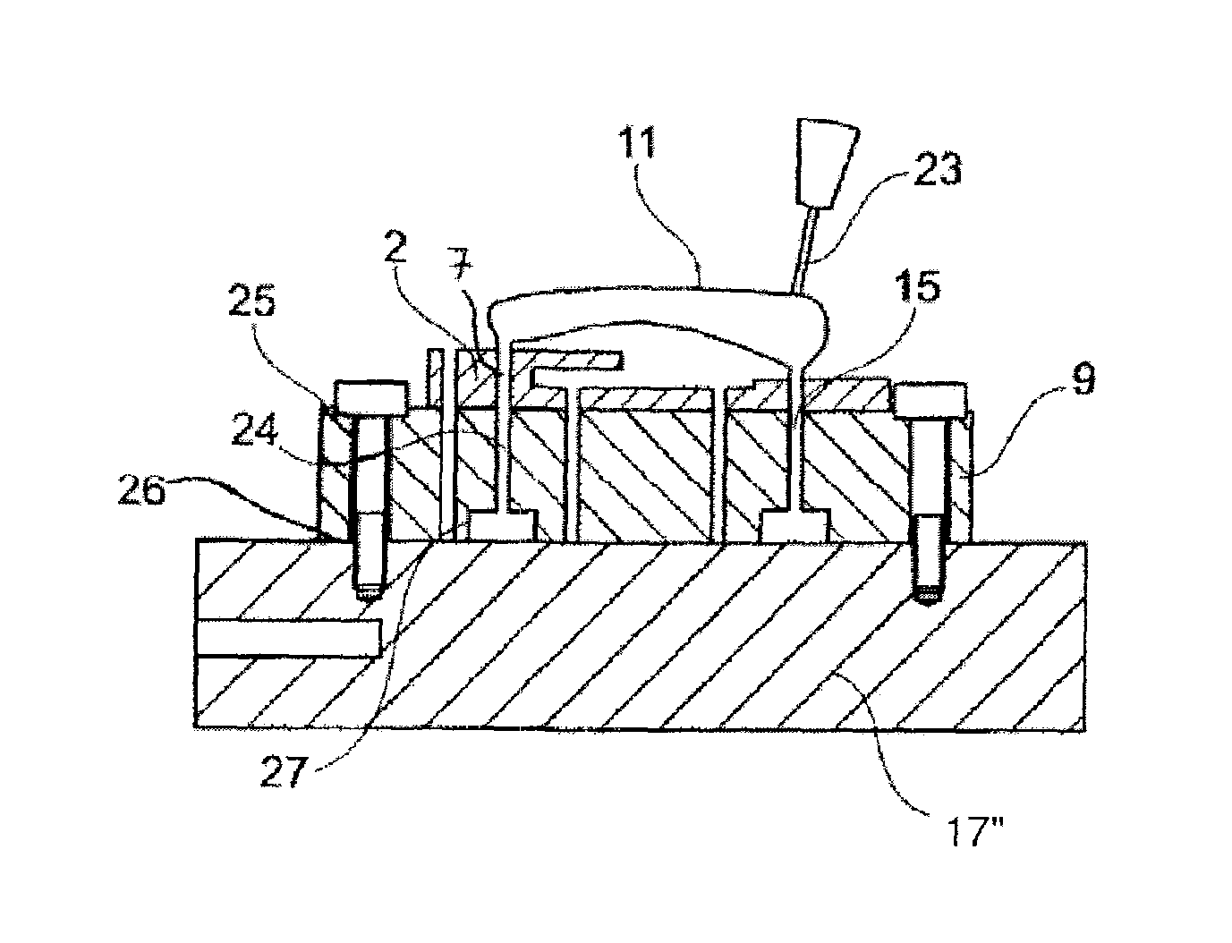
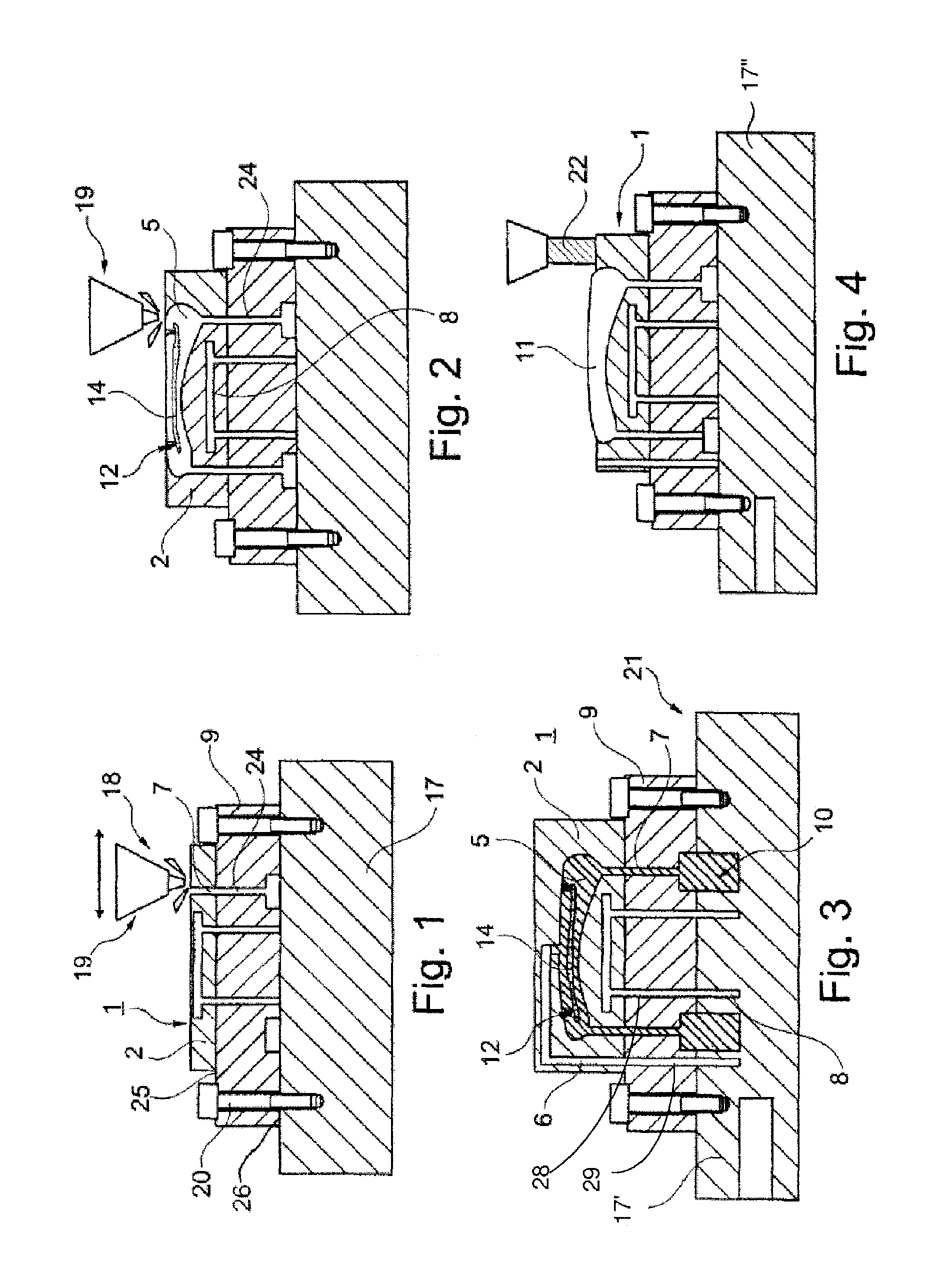
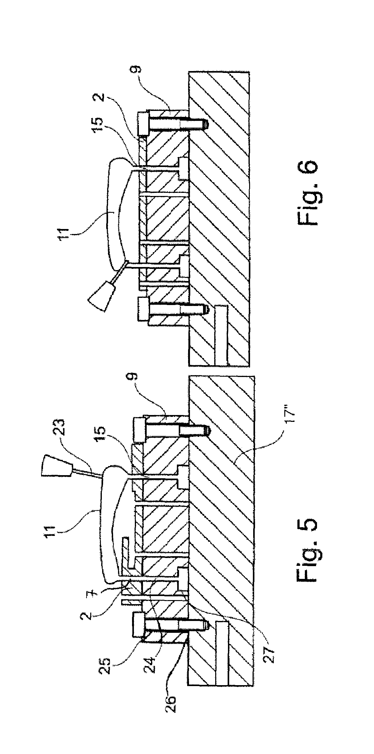
[0034]The present invention is directed to a system and method for producing an injection mold and subsequently drilling the injection mold without the need for any gripping devices. Specifically, the exemplary system and method according to the invention is directed to building a mold block layer-by-layer using a depositing technique known in the art. While depositing the layers, the feeder duct formed as an elongated opening is provided in each layer. Once the mold block is complete, a material injected into the mold will also flow into the feeder duct to form an elongated sprue extending from the molded product to a base of the system, thus holding the product in position while millig is performed. Once the molded product has been milled to required specifications, the sprue is removed therefrom to free the product from the base.

[0035]FIGS. 1 to 6 illustrate a first exemplary embodiment of a method for manufacturing an injection molded product 11 using an injection mold system 1....


PUM

PropertyMeasurementUnit
metallicaaaaaaaaaa
metallic structuresaaaaaaaaaa
mechanical stabilityaaaaaaaaaa

Abstract

A method for manufacturing an injection molded product includes producing an injection mold by building a one-piece mold block including a mold cavity sized and shaped to correspond to a desired shape of the injection molded product and a first feeder duct extending from the mold cavity and injecting a molten material into the mold cavity via the feeder duct to form an injection molded product and a sprue extending therefrom into the first feeder duct in combination with machining a portion of the injection block to expose the injection molded product and machining the injection molded product while the sprue firmly holds the product in a remaining portion of the injection mold. The product is then cut from the sprue.

Description

PRIORITY INFORMATION[0001]The present application claims priority to U.S. Provisional Application Ser. No. 61 / 371,868 entitled “Method for Manufacturing an Injection Molded Product” filed on Aug. 9, 2010 to Urs Hulliger and Hugo Flueckiger. The entire contents of this application are incorporated herein by reference thereto.FIELD OF THE INVENTION[0002]The present invention relates generally to a method for manufacturing a product by injection molding.BACKGROUND[0003]One problem associated with known injection molds is that usually a two part mold is configured in such a way that a product formed in the mold is not held in either part of the two part mold so that the product must be fixed to a machine by particular holding, gripping or fixation devices for further machining. Thus, there remains a need for an improved method for manufacturing a product by injection molding with an injection mold which permits machining or a removal of a portion of the injection mold so that the produc...

Claims


Application Information

Patent Timeline
Patent Type & Authority Patents(United States)
IPC IPC(8): B29C45/40B29C33/00B29C45/00
CPCB29C33/00B29C45/0055B29C45/40B29C2045/0058B29C45/00
Inventor HULLIGER, URSFLUECKIGER, HUGO
Owner DEPUY SYNTHES PROD INC
Why Eureka
Try Eureka