Bridge member spanning formliner joint

a technology of bridge members and formliner joints, applied in the field of formliner systems, can solve the problems of uneven wall, multiple form liner lines, and uneven wall, and achieve the effect of avoiding uneven wall, uneven wall, and avoiding uneven wall

Active Publication Date: 2014-10-07
ADVANCED FORMLINERS
View PDF33 Cites 12 Cited by
  • Summary
  • Abstract
  • Description
  • Claims
  • Application Information

AI Technical Summary

Problems solved by technology

A problem that occurs in walls formed using multiple form liners is evidence of the discontinuous, multiple form liners.
For example, adjacent form liners may not adequately seal against one another, allowing concrete slurry to migrate between, and even behind, the form liners.
This results in an uneven wall, ridges in the wall, breaks in any patterns formed in the wall, etc.
Unfortunately, these imperfections are created in the face of the resulting wall and are highly visible.
Such caulking is somewhat labor intensive and can produce intermittent results.
Another problem with prior art form liner systems stems from warping, buckling and / or bulging of the form liners.
Any such shape change can create imperfections in the resulting wall.
Although such fasteners will hold the form liners in place, the fasteners themselves can distort the face of the resulting wall.

Method used


Image

  • Bridge member spanning formliner joint
  • Bridge member spanning formliner joint
  • Bridge member spanning formliner joint

Examples


Embodiment Construction

[0033]While this invention may be embodied in many different forms, there are described in detail herein specific embodiments of the invention. This description is an exemplification of the principles of the invention and is not intended to limit the invention to the particular embodiments illustrated.

[0034]For the purposes of this disclosure, like reference numerals in the figures shall refer to like features unless otherwise indicated.

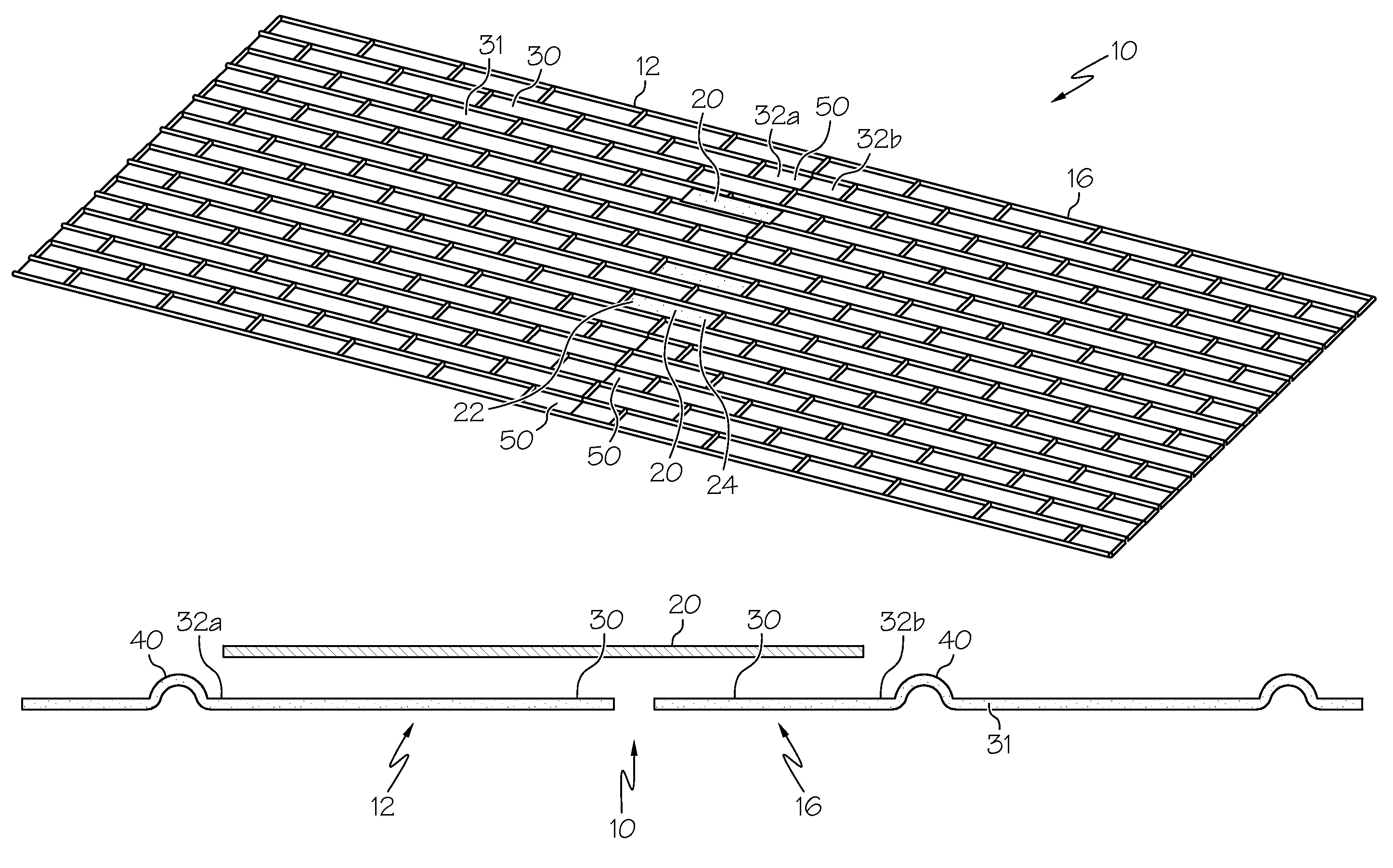
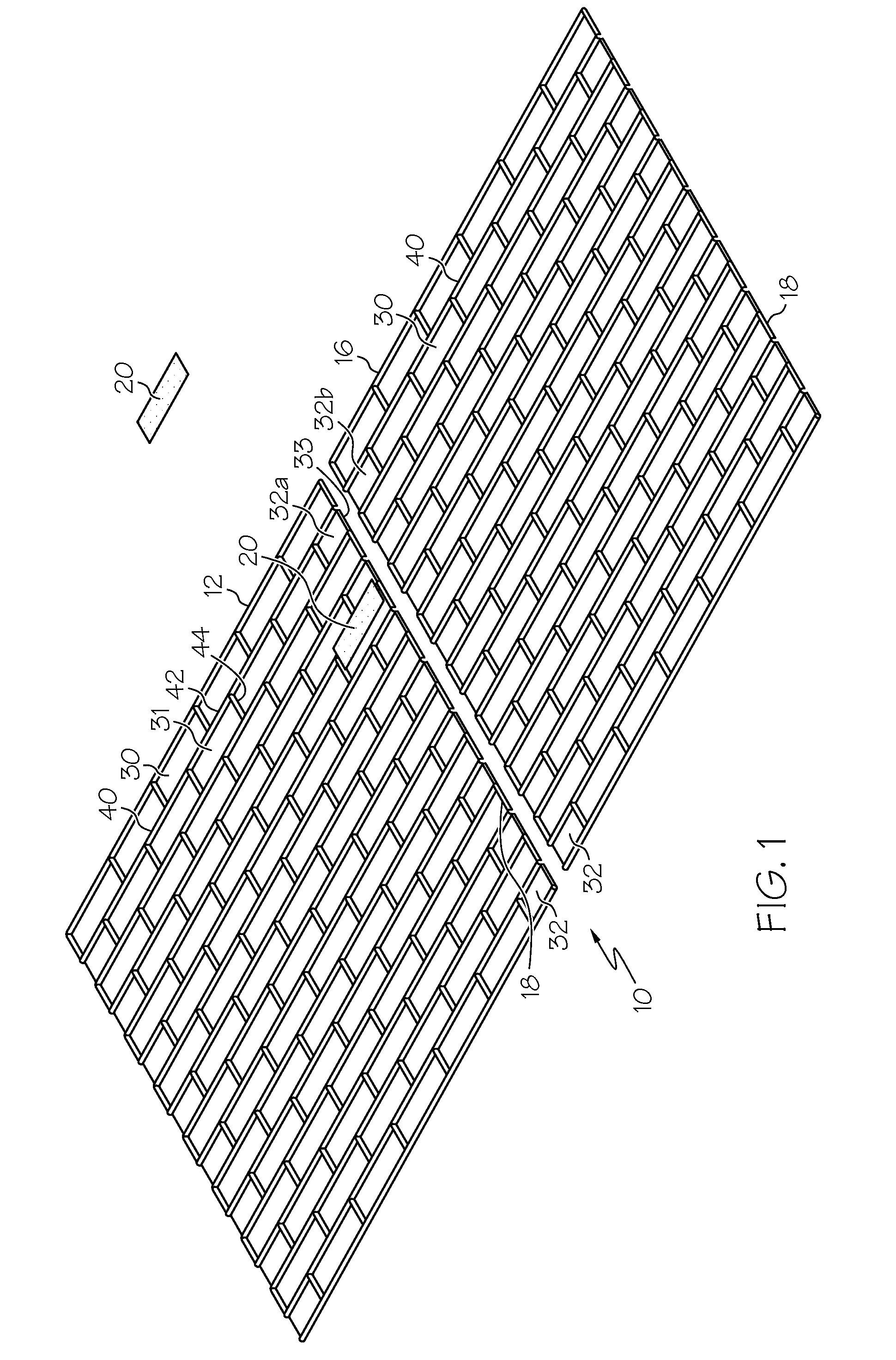
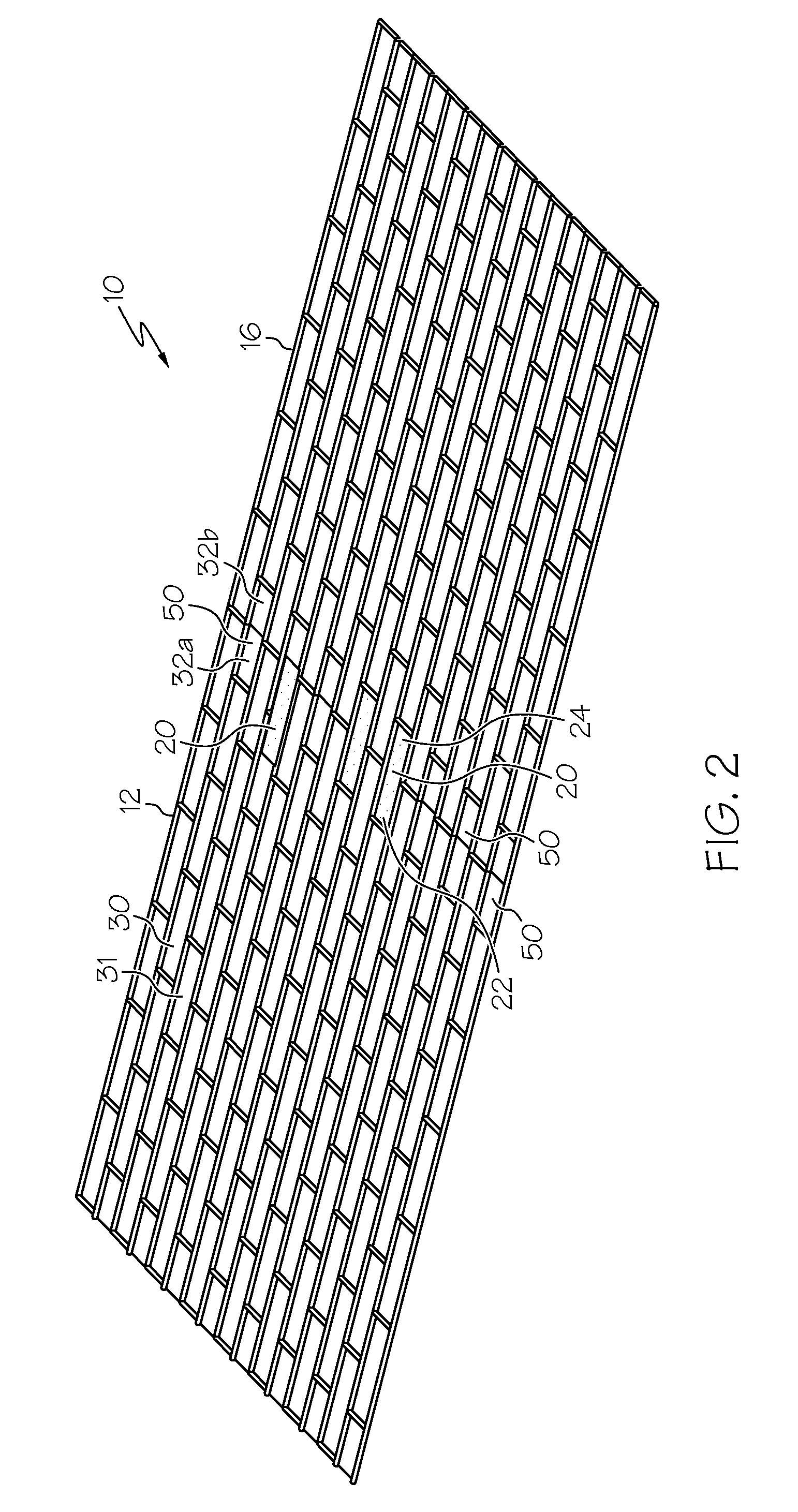
[0035]FIG. 1 shows an embodiment of a form liner system 10 comprising a first form liner 12, a second form liner 16 and a bridge member 20.

[0036]In some embodiments, the bridge member 20 is arranged to span across the two form liners 12, 16, thereby creating a continuous surface spanning a portion of the connection / overlap / joint between the two form liners 12, 16.

[0037]A form liner (e.g. 12, 16) is desirably suitable to be used as formwork for creating a cured object, such as a concrete wall. For example, a form liner 12, 16 can be laid horizontally ...


PUM

PropertyMeasurementUnit
thicknessaaaaaaaaaa
shapeaaaaaaaaaa
perimeteraaaaaaaaaa

Abstract

A form liner system comprises a first form liner, a second form liner and a bridge member. Each form liner comprises a plurality of raised portions defining a plurality of cells and at least one partial cell. The form liners are arranged such that the partial cells form a collective cell. The bridge member can be oriented in said collective cell, wherein a first portion of the bridge member is oriented in the first liner partial cell and a second portion of the bridge member is oriented in the second liner partial cell.

Description

BACKGROUND OF THE INVENTION[0001]This invention relates to a form liner system that allows for multiple form liners to be utilized while creating a product, such as a concrete wall, that appears to have been created using a single, continuous form liner.[0002]In the last several decades, the concrete industry has been advantaged by using form liners as a method of imprinting textures into concrete walls. Concrete walls created using such form liners can include three-dimensional texturing and decorative patterns. Some concrete walls are able to simulate the look of a traditional masonry structure, such as brick and mortar, rock and mortar, etc.[0003]To create a continuous wall that is larger than a given form liner, multiple form liner sheets are laid into a casting bed adjacent one another. In some instances, portions of the adjacent liners may overlap. Desirably, the individual liners are shaped and positioned such that any pattern formed in the liners will appear to be continuous...

Claims


Application Information

Patent Timeline
Patent Type & Authority Patents(United States)
IPC IPC(8): E04G17/00B28B7/00E04G9/10
CPCE04G9/10E04G17/005B28B7/0073Y10T428/24661Y10T428/24678
Inventor CALMES, SHANE
Owner ADVANCED FORMLINERS
Why Eureka
Try Eureka