
Inductive body armor

a technology of inductive body armor and body shell, applied in the direction of inductance, protective equipment, protective garments, etc., can solve the problems of physical weight of batteries, prone to replacing electronic device batteries, and large logistical burden, and achieve excellent material penetration capabilities

Inactive Publication Date: 2014-10-07
CYNETIC DESIGNS
View PDF6 Cites 41 Cited by
  • Summary
  • Abstract
  • Description
  • Claims
  • Application Information

AI Technical Summary

Benefits of technology

The invention provides a hard armor plate with either one or multiple inductive power and data nodes placed on its strike face. This allows for a single hard wired connection to each plate, simplifying power and data distribution on the soldier system. The inductive nodes operate independently, recognizing the type of device placed upon them and providing communication data. The design can be implemented in multiple configurations, with the nodes drawing power from a central power source or being controlled by a central power management system. Additionally, the invention provides a soldier system electrical network with a hard-wired connection to the plate for the exchange of power and data. The central power supply is a battery, and the processor communicates with the primary circuits and is adapted to provide power management for the controlled transfer of power to hand-held devices. Each hand-held device has its own re-chargeable power supply, which can be charged by the inductive transfer of power, allowing for hot swapping out of the central power supply without power interruption to each hand-held device when in its pocket.

Problems solved by technology

With the advent of the future soldier, this electronic burden has become an even greater contributor of the overall fighting order load and has created a considerable logistic burden with respect to the battery management of all the electronic devices the soldier is carrying.
A significant logistic issue is not only the physical weight of the batteries, but the fact that soldiers are prone to replacing their electronic device batteries whenever they think the ones installed are not sufficiently fresh.
As the devices rarely have a battery energy gauge, studies have found soldiers typically throw away up to 70% of the energy they have been carrying.
This is extremely expensive power that is thrown away from both the perspective of the soldier who carried it but never used it and the logistic replenishment support cost.
In addition soldiers do not know what batteries to take on a mission as different devices use their own type of battery and the use of equipment will change with the tactical scenario.
Frequently a soldier may not be re-supplied within the expected time frame.
The use of cables and providing power and data connections to a soldiers equipment is a considerable problem as the cables snag, connectors break and are subject to damage by the environment.
It is also very difficult to connect equipment with gloved hands in an expeditious fashion when the equipment is then to be stowed in pockets, during for example an intense tactical situation such as a fire fight.
The reconfiguration problem is compounded by the fact that all the electronic and non electronic devices and equipment require their own specialized pockets as the size and shapes of objects carried has a large range.
Many existing soldier systems cannot accommodate soldiers that shoot using the left shoulder because the pockets cannot be reconfigured.
The design of the garment may not allow for a central power management system or the need for the exchange of power management data.

Method used


Image

  • Inductive body armor
  • Inductive body armor
  • Inductive body armor

Examples


Embodiment Construction

Overview

[0098]In what follows both singular and plural language i.e. single and multiple coil and driver circuit terminology, is used interchangeably and is not intended to be limiting.

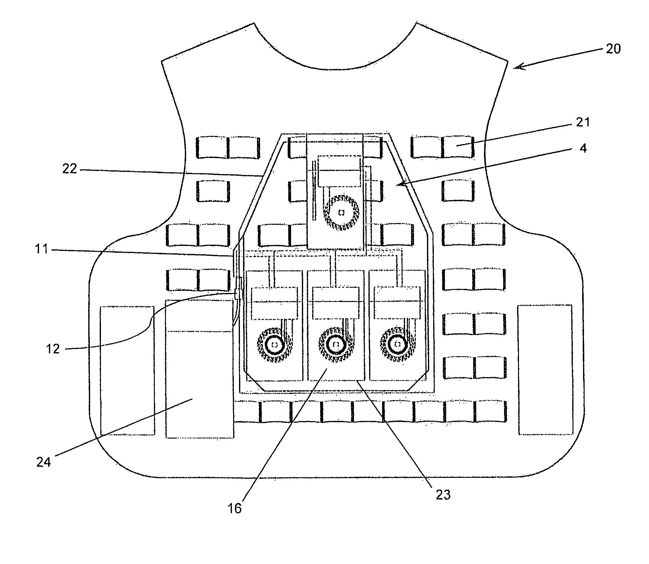
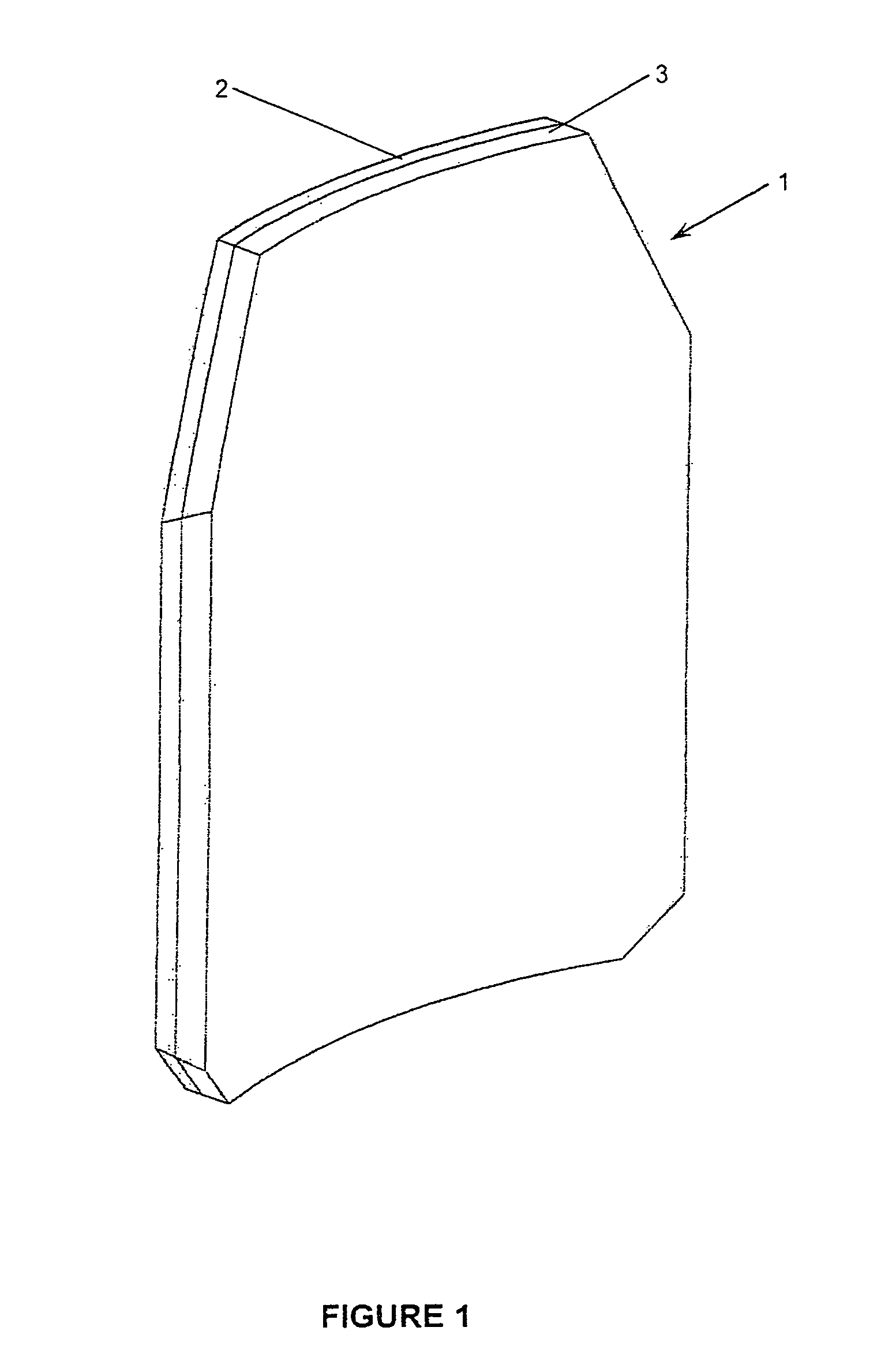
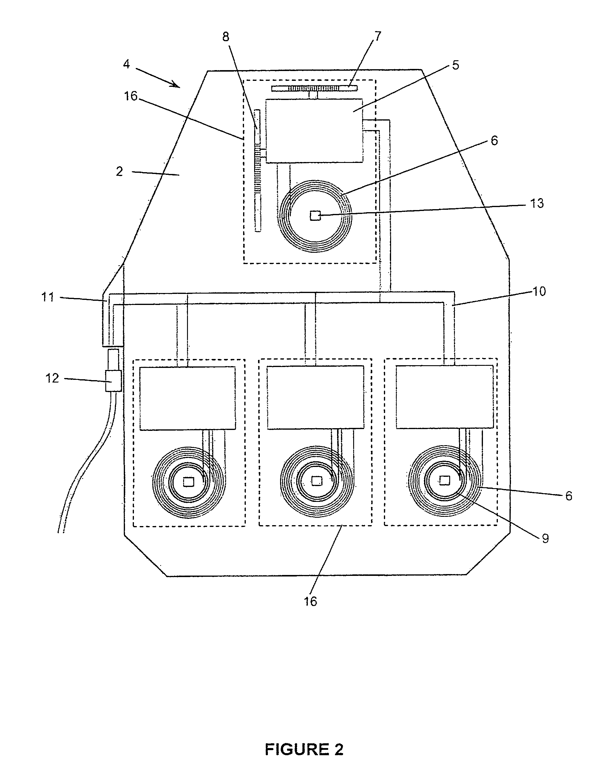
[0099]The present invention involves in one aspect the placement of a personal protective hard armour plate with integrated inductive power and data nodes into the plate pocket of a tactical garment or plate carrier (FIG. 4). The plate pocket of the garment is fitted with either fixed pockets or has provision to attach removable modular external pockets for the carriage of electronic devices that would require wireless charging and / or transmission / reception of data. No fundamental design change is required to the base garment as all of the inductive charging technology is resident on the integrated hard armour plate. The hard armour plate may have multiple wireless primary inductive power and data nodes on the outside or strike face of the plate (FIG. 2). When powered by an AC voltage from the primary...


PUM

PropertyMeasurementUnit
distanceaaaaaaaaaa
frequencyaaaaaaaaaa
thicknessaaaaaaaaaa

Abstract

A system for the inductive transmission of power from a primary coil to a secondary coil and its associated secondary circuits, and for the inductive transmission of data between the primary and secondary coils includes a hard body-armor plate mountable in a tactical garment wherein at least one primary coil is embedded in the plate behind the plate's strike-face by a substantially uniform said first depth, and wherein the primary circuits of the primary coil are adapted to be electrically connected to a central power source carried on or in cooperation with said garment, and at least one device pocket is provided for an electronic hand-held device wherein said device pocket is mountable to an outer surface of said garment so as to be in an inductively coupling position aligned over said primary coil in said plate to thereby align said secondary coil of a hand-held device in the device pocket over and into inductively coupled registry with said primary coil in the plate.

Description

CROSS REFERENCE TO RELATED APPLICATION[0001]This application claims priority from U.S. Provisional Patent Application No. 61 / 344,637 filed Sep. 3, 2010 entitled Ceramic Body Armor with Inductive Charging and Inductive Data Transfer Locations.FIELD OF THE INVENTION[0002]This invention relates to the field of tactical body-armor, and in particular to body armor employing at least one hard armor plate wherein power and data are transferred between at least one primary coil mounted behind the strike-face of the plate and a secondary coil in a hand held device mounted in a device pocket on the armor adjacent the strike-face.BACKGROUND OF THE INVENTION[0003]Soldiers have always carried a significant load when on patrol or in battle. In the recent past the load was carried in large marching packs, smaller day packs and their immediate fighting order on a load carriage vest. This vest contained all the immediate ammunition, grenades, flashlight, water, first aid and other essential smaller ...

Claims


Application Information

Patent Timeline
Patent Type & Authority Patents(United States)
IPC IPC(8): H01F27/42A41D13/015F41H1/02F41H5/04H02J5/00H04B5/00
CPCF41H1/02H02J5/005F41H5/0428A41D13/015H04B5/0037H02J7/0042H02J7/00034H02J50/402H02J50/70H02J50/80H02J50/90H02J50/12H04B5/79
Inventor SOAR, ROGER J.
Owner CYNETIC DESIGNS
Learn More