Method and conveyor system

a technology of conveyor system and conveyor belt, which is applied in the direction of motor/generator/converter stopper, dynamo-electric converter control, transportation and packaging, etc., can solve the problems of increasing the space in the conveyance system, the power-handling capacity of the frequency converter, and the size of the frequency converter as well as the size of the cooling apparatus needed to be quite large, so as to increase the power loss of the motor

Active Publication Date: 2014-10-07
KONE CORP
View PDF13 Cites 18 Cited by
  • Summary
  • Abstract
  • Description
  • Claims
  • Application Information

AI Technical Summary

Benefits of technology

[0011]In the method according to the invention, for driving the conveyor electric power is supplied to the drive machinery of a conveyor depending on the power requirement with a supply device to be selected from at least two different adjustable supply devices, and the supply device to supply power to the drive machinery is changed on the basis of the power requirement of the conveyor. With the adjustable supply device according to the invention, at least one supply magnitude, such as current, voltage and / or supply power, can be adjusted. In this case during normal operation of the conveyor and with heavy loading a supply device, preferably a soft starter, can be used, in which the power supply is adjusted with switches, which are intended to be connected with a larger current and at a smaller switching frequency, preferably at the frequency of the electricity network. When the conveyor is running idle / with low loading, on the other hand, it is possible to use a supply device, preferably an inverter, the switches of which are intended to be connected with a smaller current and at a larger switching frequency. The inverter used does not in this case either need to be a regenerative braking type, but instead can be an inverter comprising a rectifying bridge formed from diodes. With this type of inverter power can be supplied just from the electricity network towards the drive machinery of the conveyor; however, an advantage of the inverter in question is inter alia a simple structure and a cheap price. As the power requirement of the conveyor and, on the other hand, the switching frequency of the switches increase, the power losses of the supply device also increase, so that by means of the solution according to the invention the power losses of the supply devices can be minimized, in which case also the size of the devices / necessary cooling apparatus decreases. Since in the invention power is supplied to the drive machinery of the conveyor with an adjustable supply device also during the normal operating speed of the conveyor and during essentially heavy loading, the overexcitation of the conveyor, and thus the energy consumption of the conveyor, can be reduced in all the operating situations of the conveyor, also during heavy loading.
[0012]In a preferred embodiment of the invention the amplitudes of the voltages to be supplied with the aforementioned at least two different adjustable supply devices are adjusted in the changeover situation of the supply device. In some embodiments the amplitudes at the fundamental frequencies of the voltages to be supplied with the aforementioned at least two different adjustable supply devices are adjusted to be essentially equal in the changeover situation of the supply device. In a preferred embodiment of the invention the supply device is changed when it is estimated that the power requirement of the conveyor will increase to be larger than the permitted power-handling capacity of the inverter. The permitted power-handling capacity of the inverter is determined on the basis of inter alia the current endurance of the power semiconductors of the inverter and / or the dimensioning of the cooling apparatus of the inverter. In a preferred embodiment of the invention the amplitude of the fundamental frequency of the voltage to be supplied with the soft starter is gradually increased in connection with a change of the supply device such that the amplitude of the supply voltage increases in a ramp towards the maximum value. In this way the change of the supply device can be performed smoothly without an undesirable torque impact or nudge being produced in the electric motor of the drive machinery.
[0016]In some embodiments the frequency of the fundamental frequency of the voltage to be supplied with the inverter is adjusted to be just as large as the frequency of the fundamental frequency of the voltage to be supplied with the soft starter in the changeover situation of the supply device and also the phase of the fundamental frequency of the voltage to be supplied to the drive machinery with the inverter is adjusted to be essentially the same as the phase of the fundamental frequency of the voltage to be supplied to the drive machinery with the soft starter in the changeover situation of the supply device. In this way the accuracy of the synchronization of the supply voltages can be further improved in the changeover situation of the supply device.
[0019]The conveyor system according to the invention comprises drive machinery for driving the conveyor. The conveyor system also comprises at least two different, adjustable supply devices, fitted to supply electric power at different times to the drive machinery of the conveyor. In addition, the conveyor system comprises a control device, which is configured to form a control signal for changing the supply device supplying power to the drive machinery on the basis of the power requirement of the conveyor. In a preferred embodiment of the invention the aforementioned at least two different adjustable supply devices are arranged to adjust the amplitudes of the voltages they supply in the changeover situation of the supply device. In some embodiments of the invention the aforementioned at least two different adjustable supply devices are arranged to adjust the amplitudes of the fundamental frequencies of the voltages they supply in the changeover situation of the supply device to be essentially equal. One supply device according to the invention is an inverter; another supply device according to the invention is a soft starter. In a preferred embodiment of the invention the soft starter is configured to gradually increase the amplitude of the voltage to be supplied with the soft starter in connection with a change of the supply device. The soft starter is intended to be connected with a larger current and with a smaller switching frequency than the inverter. The inverter is used when running the conveyor on idle / with low loading and the soft starter is used during a period of heavy loading of the conveyor. In a preferred embodiment of the invention the inverter is fitted to supply voltage to the supply leads of the drive machinery of the conveyor, the amplitude and frequency of the fundamental frequency of which voltage are adjustable. In a preferred embodiment of the invention the soft starter comprises thyristors fitted between the alternating electricity source and the drive machinery such that at least one thyristor is in each phase connected in series between a phase of the alternating electricity source and a phase conductor of the drive machinery. Since the power losses of the thyristors are generally smaller, owing inter alia to a lower switching frequency as well as to the structural properties of the thyristors, than power semiconductors (such as IGBT transistors or MOSFET transistors) of corresponding size used in the switches of the inverter, the power losses of the supply devices can be minimized by means of the combination according to the invention of thyristors and an inverter, in which case also the size of the devices / necessary cooling apparatus decreases. Since in the invention the amplitude of the voltage to be supplied to the drive machinery of the conveyor can be adjusted with the soft starter also during the normal operating speed of the conveyor and during essentially heavy loading, the overexcitation of the conveyor, and thus the energy consumption of the conveyor, can be reduced in all the operating situations of the conveyor, also during heavy loading.
[0025]In a preferred embodiment of the invention the soft starter is fitted to supply voltage that is adjustable in its amplitude but of essentially constant frequency from the alternating electricity source to the supply leads of the drive machinery of the conveyor. Consequently the amplitude of the supply voltage of the drive machinery of the conveyor can be adjusted on the basis of the power requirement of the conveyor when the loading of the conveyor varies also during essentially heavy loading. When the power requirement / loading of a conveyor varies, too large an amplitude of the supply voltage of the drive machinery produces an unnecessarily large excitation current of the motor. Growth of the excitation current on the other hand increases the power losses of the motor, e.g. in the form of line losses and eddy current losses.

Problems solved by technology

A problem with this solution is that the power-handling capacity of the frequency converter must be dimensioned according to the full load of the conveyor and according to the power requirement of the normal operating speed.
In this case the size of the frequency converter as well as the size of the cooling apparatus needed increases to be quite large, in which case in addition to power losses and possible heat transfer problems, one problem is also the space in the conveyance system that needs to be reserved for the frequency converter / cooling apparatus.
Since synchronization with the network / increasing of the amplitude of the voltage supplied must, owing to the underdimensioned frequency converter, be performed before the loading of the conveyor has increased too much, from the moment of the closing of the contactors onwards the drive machinery of the conveyor operates at least for some time overexcited with an unnecessarily large voltage.
Overexcitation increases the current requirement of the drive machinery and at the same time also the energy consumption of the conveyor increases.
On the other hand, the loading of the conveyor can vary to some extent also with heavy loading during normal operation of the conveyor, so that also during normal operation overexcitation increases the energy consumption of the conveyor.

Method used


Image

  • Method and conveyor system
  • Method and conveyor system
  • Method and conveyor system

Examples


Embodiment Construction

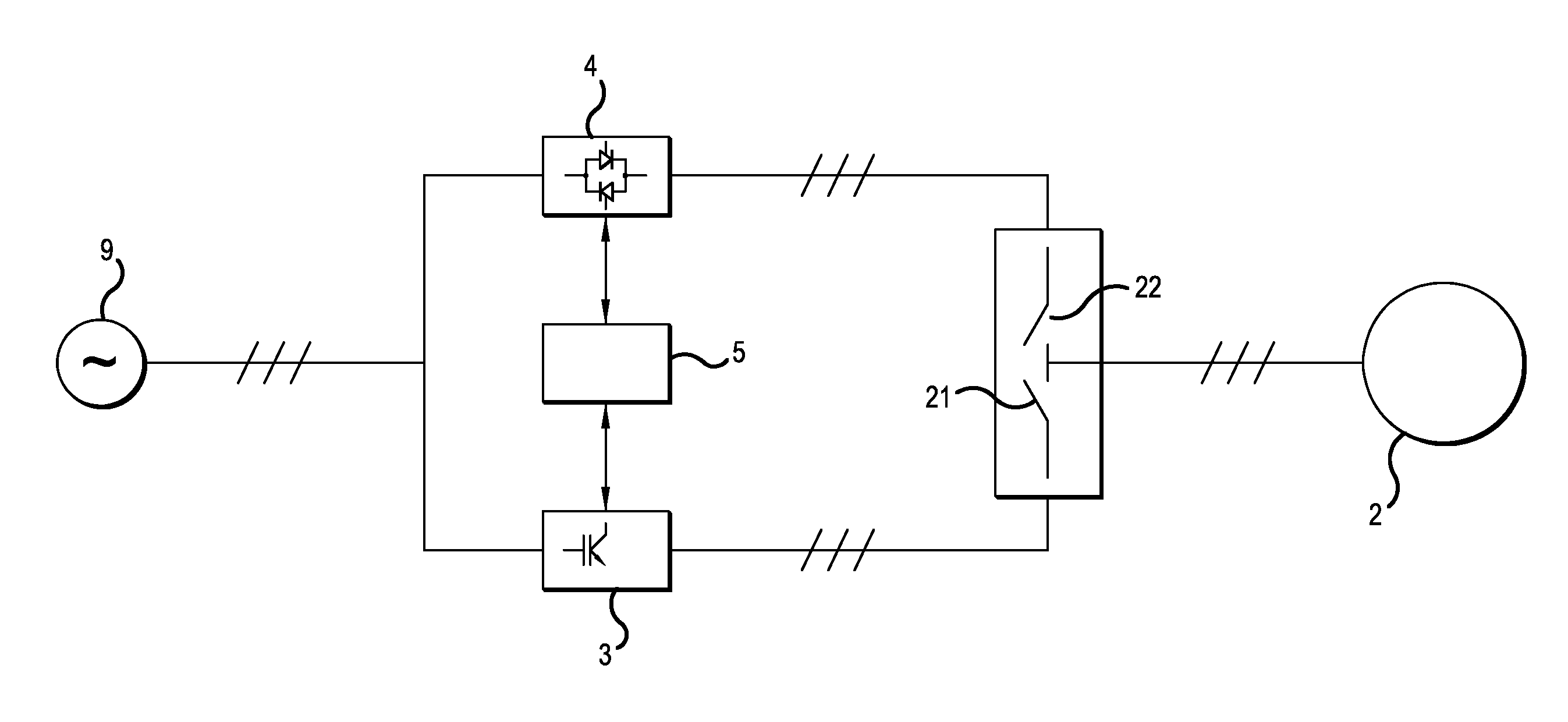
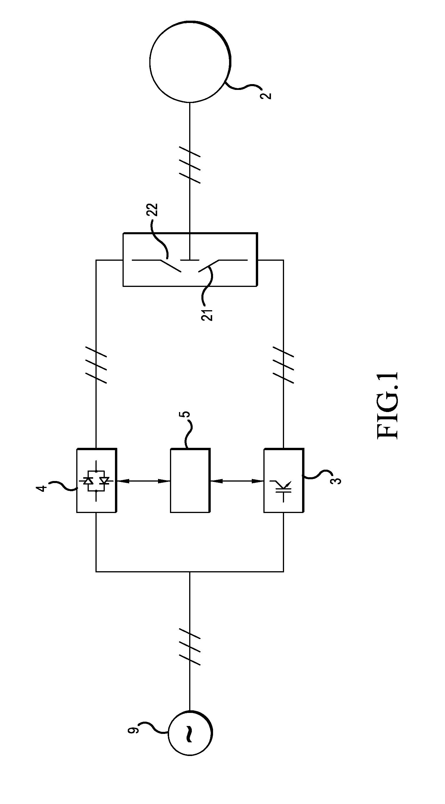
[0038]As presented in FIG. 1, the power supply to the induction motor that functions as the power-producing part of the drive machinery 2 of the conveyor occurs alternatively either with an inverter 3 or with a soft starter 4. The inverter 3 is used when the power requirement of the conveyor is small, such as when the conveyor is running idle, and the soft starter 4 is used during a period of a large power requirement of the conveyor. Power is supplied to the stator winding of the induction motor, which stator winding has a delta connection.

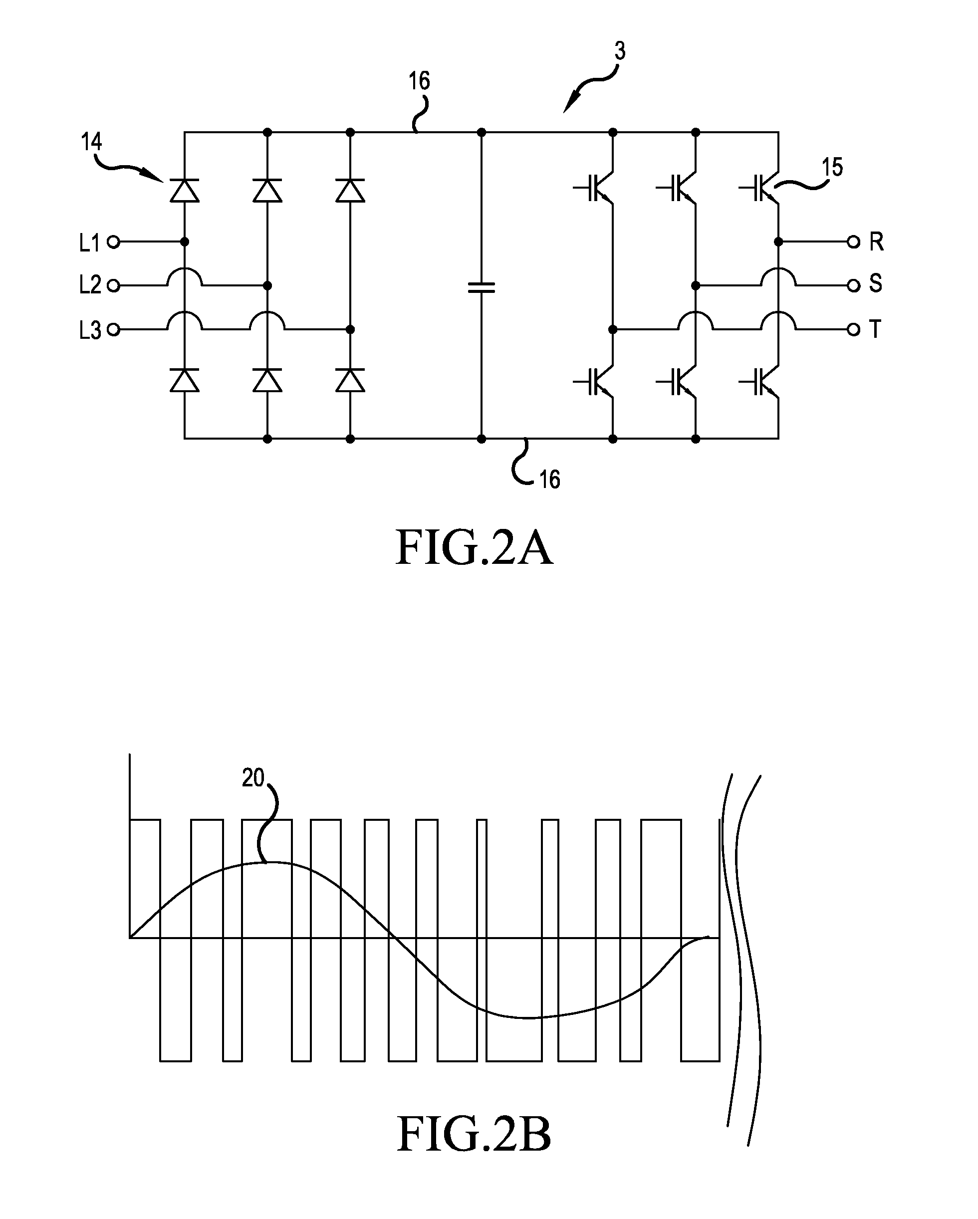
[0039]FIG. 2a presents in more detail an inverter to be used in the embodiment of FIG. 1. The inverter 3 comprises a rectifying bridge 14, which is implemented with diodes, to be connected to the phases L1, L2, L3 of a three-phase electricity network 9. In addition, the inverter 3 comprises a motor bridge 15, which is implemented with IGBT transistors, to be connected to the supply leads R, S, T of the three-phase induction motor of the drive mac...


PUM


Abstract

A conveyor system and a method for driving a conveyor are disclosed. In the method, electric power is supplied to the drive machinery of a conveyor depending on the power requirement with a supply device to be selected from at least two different adjustable supply devices, and the supply device supplying power to the drive machinery is changed on the basis of the power requirement of the conveyor.

Description

CROSS-REFERENCE TO RELATED APPLICATIONS[0001]This application is a Continuation of PCT International Application No. PCT / US2011 / 055738 filed on Oct. 11, 2011, which claims priority under 35 U.S.C 119(a) to U.S. Application No. 61 / 429,609 filed Jan. 4, 2011, all of which are hereby expressly incorporated by reference into the present application.FIELD OF THE INVENTION[0002]The invention relates to power supply solutions of conveyor systems and more particularly to power supply solutions of escalators, travelators and moving ramps.BACKGROUND OF THE INVENTION[0003]A conveyor comprises a track, along which a load is moved with the conveyor. The track of a conveyor has e.g. pallets, steps or corresponding to be moved, supported on which the load to be transferred, such as passengers or freight, is moved. Moving of the load occurs with drive machinery, which in addition to an electric motor can comprise e.g. a rotating gear wheel, which connects mechanically to the track of the conveyor, ...

Claims


Application Information

Patent Timeline
Patent Type & Authority Patents(United States)
IPC IPC(8): H02P23/02B66B25/00
CPCH02P23/02B66B25/00Y02B50/00
Inventor BOOM, ANTHONY, S.
Owner KONE CORP
Why Eureka
Try Eureka