Buffer assembly and application method thereof

a buffer layer and assembly technology, applied in the direction of identification means, electrical apparatus casings/cabinets/drawers, instruments, etc., can solve the problems of deformation of the buffer layer, display panel damage or absorption, and difficulty in accurately attaching the buffer layer between the display panel and the transparent glass shell

Inactive Publication Date: 2014-10-07
FU TAI HUA IND SHENZHEN +1
View PDF7 Cites 0 Cited by
  • Summary
  • Abstract
  • Description
  • Claims
  • Application Information

AI Technical Summary

Benefits of technology

[0006]However, the display panel typically has a narrow border at least two sides thereof, and the buffer layer correspondingly has a small width at each of at least two sides thereof. As a result, the buffer layer is liable to become deformed, either during the process of being adhered to the display panel, or even before the adhering process is begun. Once the buffer layer has become deformed, it is difficult to accurately attach the buffer layer between the display panel and the transparent glass shell. Some gaps are liable to be formed between a surface of the buffer layer and the display panel, and / or between an opposite surface of the buffer layer and the transparent glass shell. As a consequence, the watertightness of the assembly including the display panel and the transparent glass shell may be defective, and the quality of the electronic apparatus may deteriorate rapidly over time.

Problems solved by technology

However, the display panel is liable to be damaged or abraded in the assembly process or during transportation of the electronic apparatus after its manufacture.
As a result, the buffer layer is liable to become deformed, either during the process of being adhered to the display panel, or even before the adhering process is begun.
Once the buffer layer has become deformed, it is difficult to accurately attach the buffer layer between the display panel and the transparent glass shell.
Some gaps are liable to be formed between a surface of the buffer layer and the display panel, and / or between an opposite surface of the buffer layer and the transparent glass shell.
As a consequence, the watertightness of the assembly including the display panel and the transparent glass shell may be defective, and the quality of the electronic apparatus may deteriorate rapidly over time.

Method used


Image

  • Buffer assembly and application method thereof
  • Buffer assembly and application method thereof
  • Buffer assembly and application method thereof

Examples


first embodiment

[0029]Referring to FIG. 6, a flowchart of a method for adhering the buffer assembly 1 to the display panel 10 is shown. The method includes the following steps.

[0030]In step S1, the buffer assembly 1 and the display panel 10 to be adhered with the buffer assembly 1 are provided.

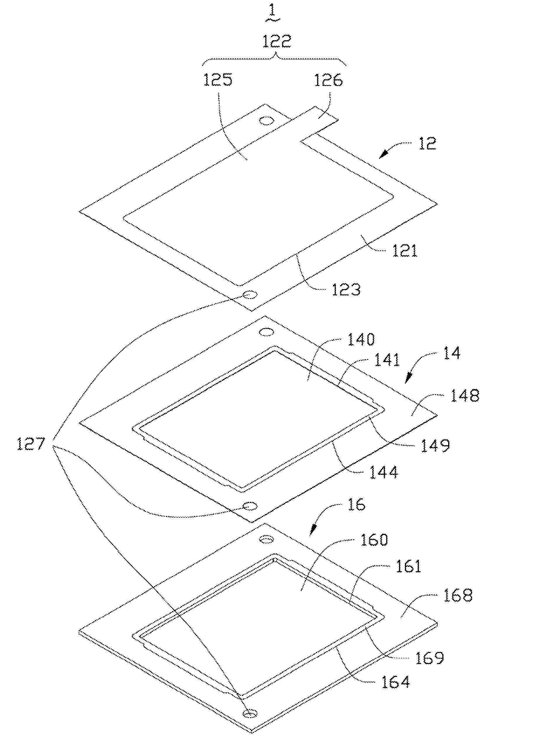
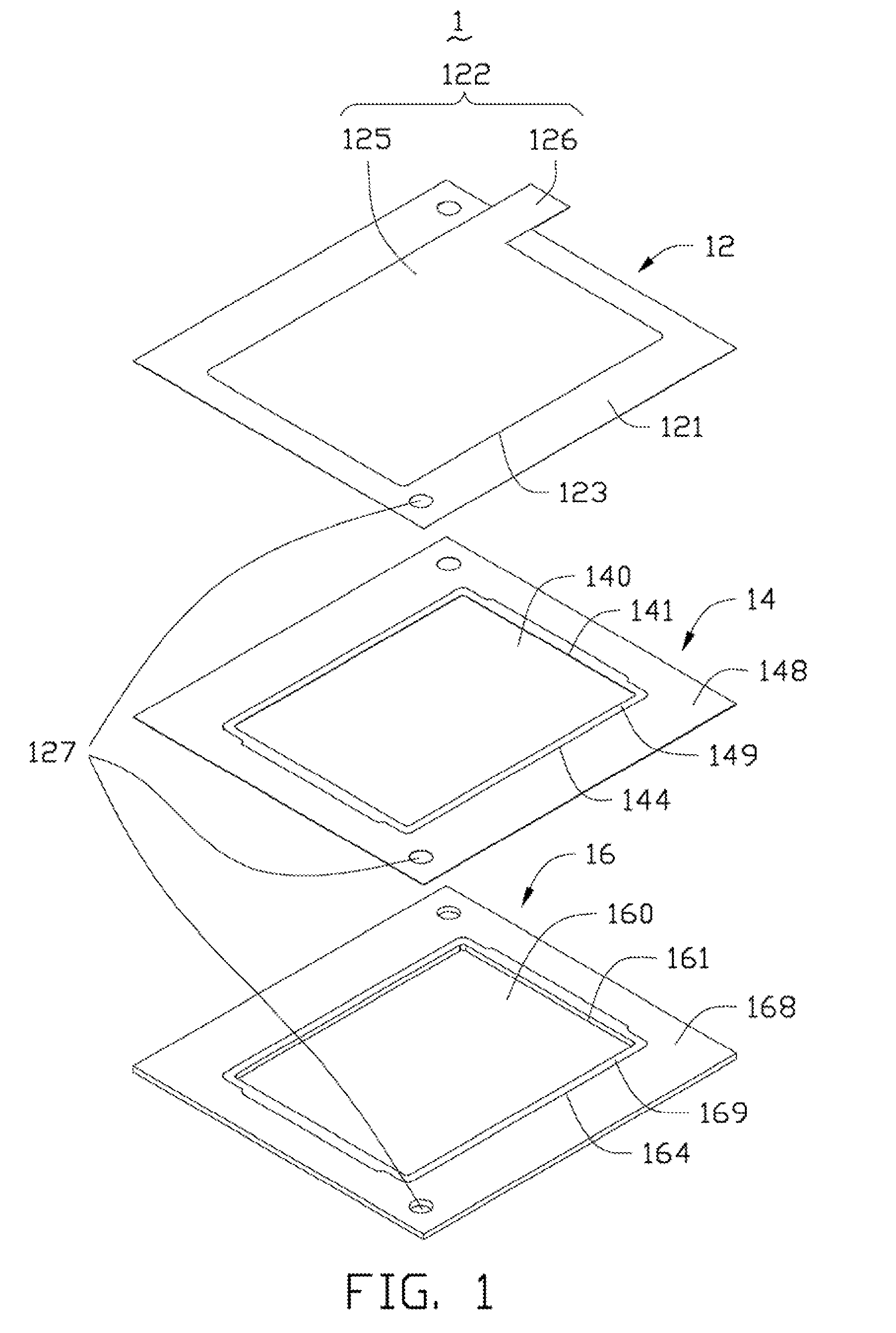
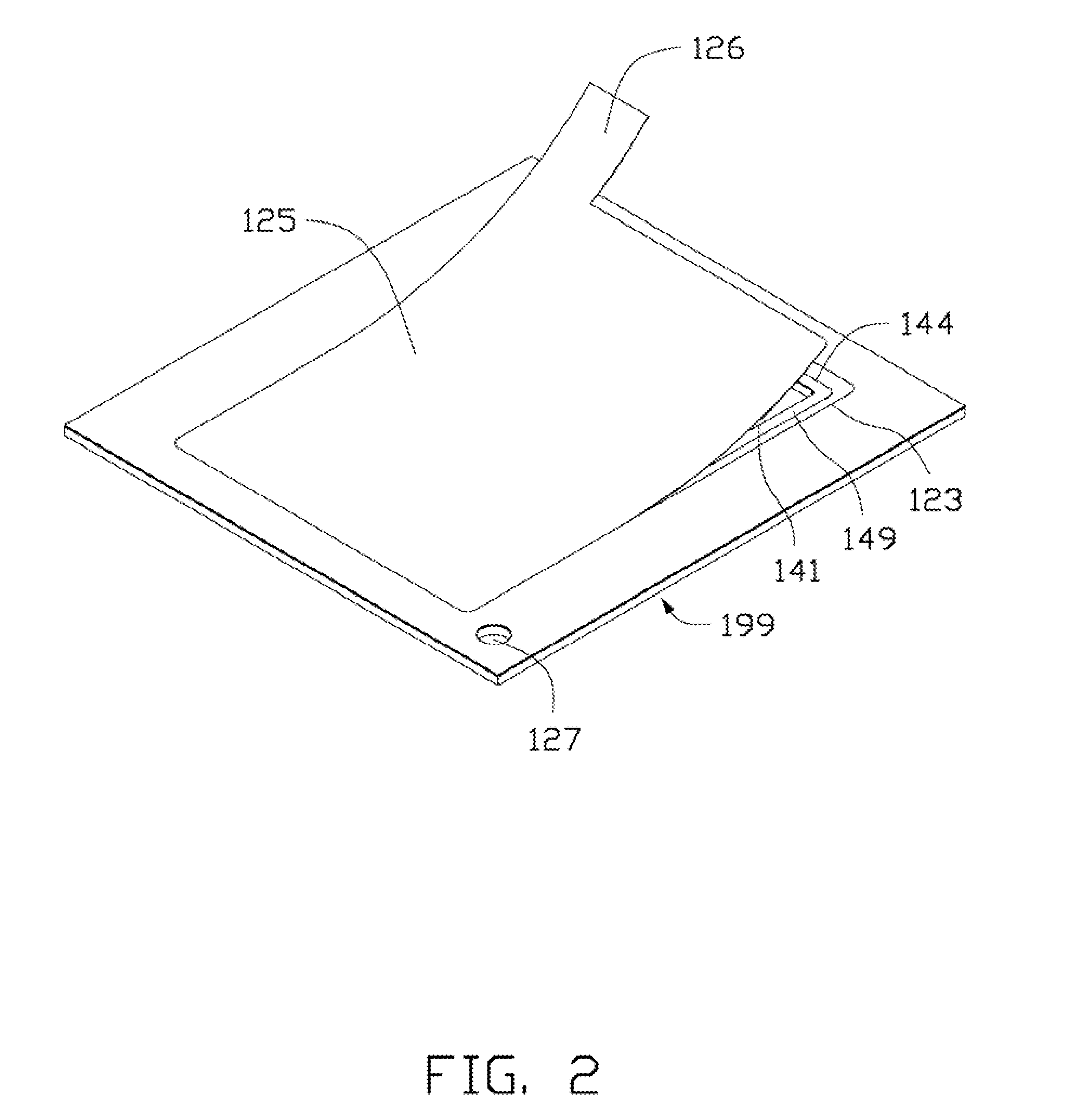
[0031]In step S2, the first release portion 122 of the release paper 12 is peeled from the buffer assembly 1. The first release portion 122 is manually peeled from the release paper 12 by holding the extension end 126, and the peeling occurs along the third cutting line 123. After the first release portion 122 has been peeled off, the first and second openings 160, 140, the first adhesive portion 149, and part of the second adhesive portion 148 are exposed.

[0032]In step S3, the buffer assembly 1 is aligned with and adhered to the display panel 10. In this embodiment, the areas of the first and the second openings 160, 140 are substantially equal to that of the display portion 11, and the area of the first ad...

second embodiment

[0035]Referring to FIG. 7, a flowchart of a method for adhering the buffer assembly 1 to the display panel 10 is shown. The method includes the following steps.

[0036]In step S1′, the buffer assembly 1, the display panel 10 to be adhered with the buffer assembly 1, and an assembling device 3 are provided.

[0037]Referring to FIG. 8, an isometric view of part of the assembling device 3 is shown. The assembling device 3 includes a supporting platform 32, a cover board 37, and a head 35. The supporting platform 32 is used to support the buffer assembly 1. The cover board 37 defines a rectangular opening 376 therein, for allowing the display panel 10 to pass therethrough. The cover board 37 is used to cover a part of the strength enhanced portion 199 of the buffer assembly 1. The head 35 is used to apply a force on the display panel 10.

[0038]Two position poles 327, a plurality of position protrusions 329, and a plurality of drawing holes 321 are disposed on the supporting platform 32. The...


PUM

PropertyMeasurementUnit
areaaaaaaaaaaa
adhesiveaaaaaaaaaa
transparentaaaaaaaaaa

Abstract

A buffer assembly includes a buffer body and an adhesive layer on the buffer body. The buffer body includes a buffer portion and a mounting portion surrounding the buffer portion. The adhesive layer includes a first adhesive portion and a second adhesive portion surrounding the first adhesive portion. The first adhesive portion and the second adhesive portion respectively correspond to the buffer portion and the mounting portion. A first cutting line is disposed between the buffer portion and the mounting portion such that the mounting portion is separable from the buffer portion along the first cutting line. A second cutting line is disposed between the first adhesive portion and the second adhesive portion such that the second adhesive portion is separable from the first adhesive portion along the second cutting line. The second cutting line superposes the first cutting line.

Description

BACKGROUND[0001]1. Technical Field[0002]The present disclosure generally relates to buffer assemblies, and particularly to a buffer assembly for an electronic device and an application method of the buffer assembly.[0003]2. Description of Related Art[0004]Display devices, such as liquid crystal displays (LCDs), are employed in electronic apparatuses for displaying images and in many instances for providing an operational interface for a user to adjust parameters of the electronic apparatus. A display panel, such as an LCD display panel or an organic light emitting diode (OLED) display panel, is normally provided on a surface of the electronic apparatus so that people can view the images shown by the display panel conveniently. In manufacturing, the display panel is attached to the surface of the electronic apparatus. However, the display panel is liable to be damaged or abraded in the assembly process or during transportation of the electronic apparatus after its manufacture.[0005]T...

Claims


Application Information

Patent Timeline
Patent Type & Authority Patents(United States)
IPC IPC(8): B65D81/05B65D85/48G02F1/1333
CPCB65D81/05B65D85/48G02F1/133308G02F2202/28G02F2201/503G02F2001/133322Y10T156/1052Y10T428/15G02F1/133322
Inventor HUANG, QUNCHOU, CHE-YUZHU, TAI-SHANWU, JI-PING
Owner FU TAI HUA IND SHENZHEN
Why Eureka
Try Eureka