Method using a blanking signal to reduce the leakage transmitter-receiver

a transmitter-receiver and blanking technology, applied in the field of mobile communication end devices, can solve the problems of reducing the performance of sps receivers in particular, increasing power consumption, and reducing the efficiency of communication end devices, so as to reduce efficiently reducing the effect of self interference within a communication, and improving the utilization of sps blanking

Active Publication Date: 2014-10-07
TELEFON AB LM ERICSSON (PUBL)
View PDF18 Cites 3 Cited by
  • Summary
  • Abstract
  • Description
  • Claims
  • Application Information

AI Technical Summary

Benefits of technology

[0016]According to an embodiment of the present invention the control signal comprises an enable signal and / or a disable signal for the further receiver. This may provide the advantage that the operation of the further receiver can be controlled in a very simple but effective manner. Thereby, a blanking or a disabling of the operation of the further receiver can be realized in particular at times, when there is expected a strong self interference between the transmitter and the further receiver.
[0044]According to a further embodiment of the present invention the further receiver comprises a Near Field Communication receiver and in particular a Radio Frequency Identification receiver. This may provide the advantage that the described concept for reducing self interference within a communication end device can be applied with a technology, which is expected to be used more and more in daily life of communication end users.

Problems solved by technology

However, such combined communication end devices may also exhibit certain shortcomings such as increased power consumption and a reduced performance.
One marked disadvantage inherent in many combined SPS receiver and radio communication device is the decreased performance of the SPS receiver in particular when a radio transmitter of the radio communication device is active.
Although the radio transmitter of the radio communication device and the SPS (radio) receiver typically operate in completely different frequency bands, the described self interference is often troublesome because of at least some of the following reasons: (A) The spatial distance between the radio transmitter and the SPS receiver is small.
The known self interference countermeasure by disabling a GPS receiver during an active radio transmitter has the disadvantage that with an increasing activity of the radio transmitter, the GPS receiver will be increasingly blanked.
In particular as Long Term Evolution (LTE) technology typically implies a continuous transmission of a cellular transceiver, the known blanking solution may not work since the GPS receiver will be disabled (almost) all the time.

Method used


Image

  • Method using a blanking signal to reduce the leakage transmitter-receiver
  • Method using a blanking signal to reduce the leakage transmitter-receiver
  • Method using a blanking signal to reduce the leakage transmitter-receiver

Examples


Embodiment Construction

[0059]The illustration in the drawing is schematically.

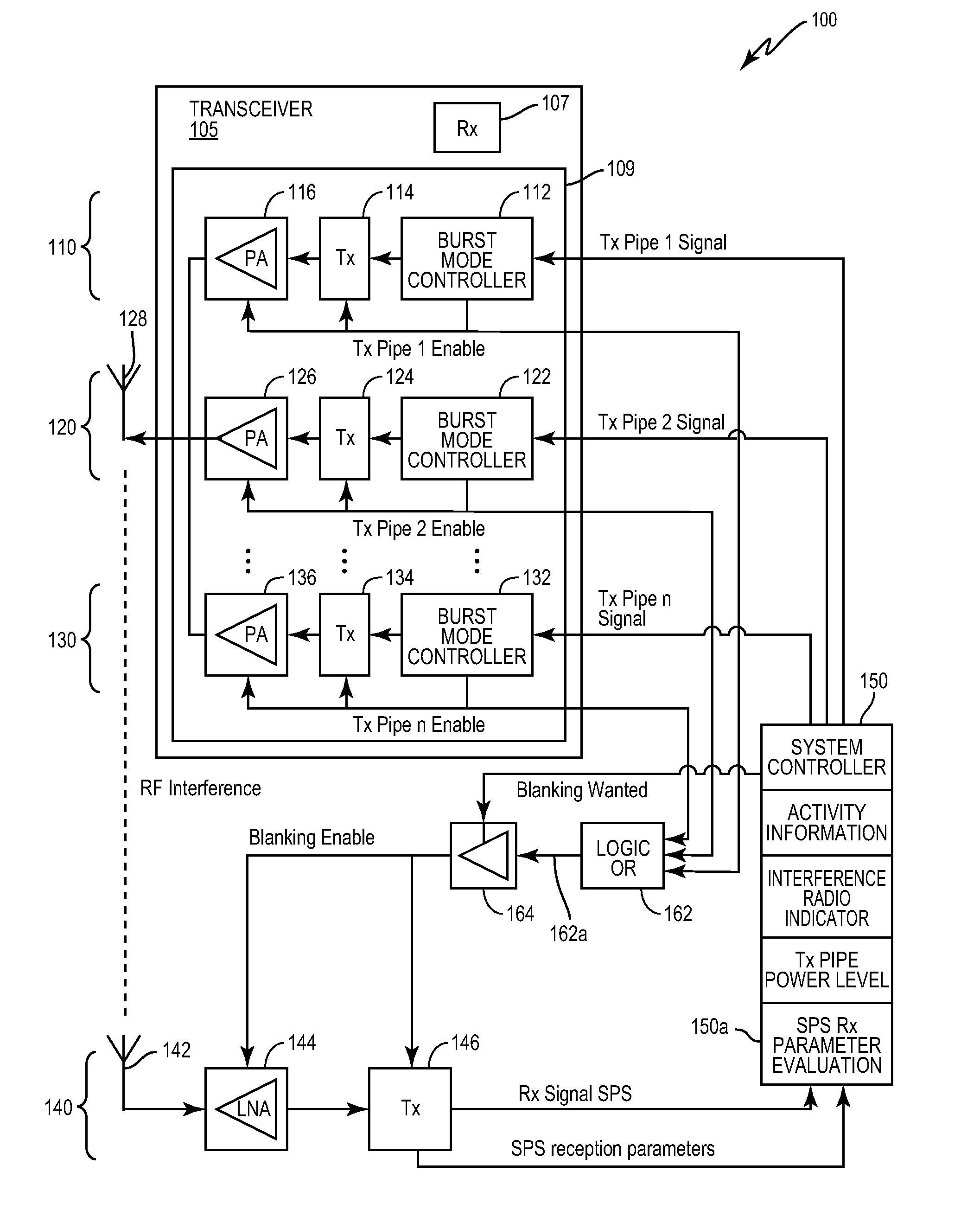
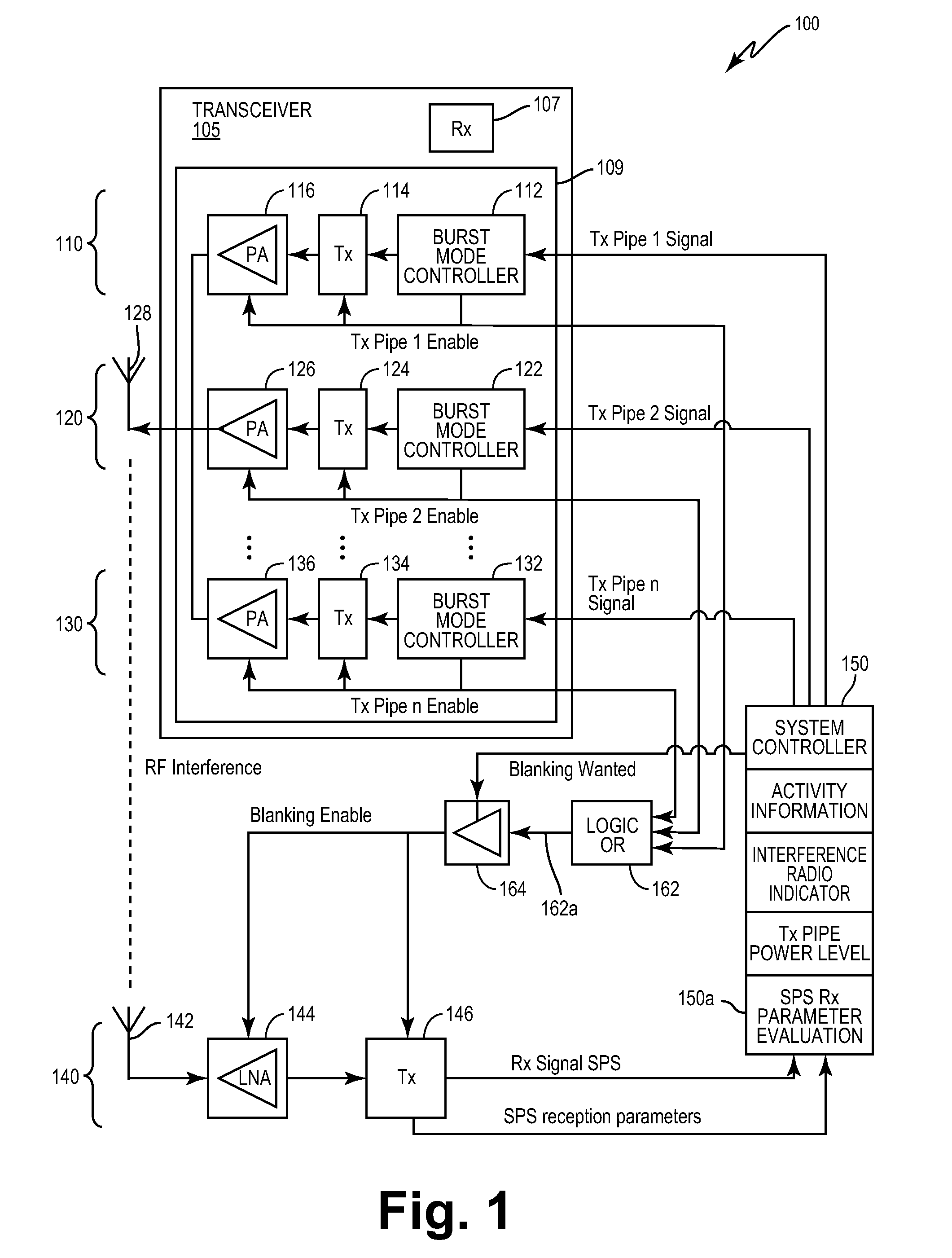
[0060]FIG. 1 shows a structural diagram of a communication end device 100 in accordance with an embodiment of the invention. The communication end device 100 is a multiband and multimode user equipment. Specifically, apart from a cellular radio transceiver 105 with a cellular transmitter 109 and a cellular receiver 107 the communication end device 100 comprises a further receiver 140. According to the embodiment described here, the further receiver 140 is a satellite positioning system (SPS) receiver 140.

[0061]The communication end device 100 comprises a control unit 150, which is connected both to the transmitter 109 of the cellular radio transceiver 105 and to the SPS receiver 140. The control unit is configured for controlling the operation of the cellular transmitter 109 and in particular of the SPS receiver 140.

[0062]As can be seen from FIG. 1, the cellular transmitter comprises a plurality of cellular transmission pipes. I...


PUM


Abstract

It is described a communication end device comprising (a) a radio transceiver comprising a receiver for receiving radio signals from a transmitting network entity of a cellular telecommunication network and a transmitter (110, 120, 130) for transmitting radio signals to a receiving network entity of the cellular telecommunication network, (b) a further receiver (140) for receiving a further radio signal, and (c) a control circuit (150, 162, 164), which is coupled to the radio transceiver and to the further receiver (140). The control circuit (150, 162, 164) is configured for generating a control signal for controlling the operation of the further receiver (140). Thereby, the control signal is based on a synchronization signal being related to a time dependent transmission scheme of the transmitter (110, 120, 130) and on an information about the current operational state of the radio transceiver. It is further described a method for controlling the operation of such a communication end device (100) and a program element and a computer-readable medium having stored such a program element, which is adapted for controlling and / or for carrying out this operation control method.

Description

FIELD OF THE INVENTION[0001]The present invention relates to the technical field of mobile communication end devices, which comprise a transmitter and at least two receivers, wherein the two receivers are capable of receiving two different types of radio signals. Specifically, the present invention relates to a mobile communication end device comprising a transmitter and at least two receivers and to a method for operating such a mobile communication end device, wherein self interference between the transmitter and at least one of the two receivers can be minimized. Further the present invention relates to a program element and to a computer-readable medium with such a program element, which is adapted for controlling and / or for carrying out the described method.BACKGROUND OF THE INVENTION[0002]The use of portable personal communication devices, such as cellular phones, Personal Digital Assistant (PDA), a notebook computer and / or any other movable communication devices being configu...

Claims


Application Information

Patent Timeline
Patent Type & Authority Patents(United States)
IPC IPC(8): H04W88/06H03G3/30H04B1/38H04B1/52
CPCH03G3/3078H04B1/525H04B1/3805H04W88/06
Inventor NEUMANN, MARKUS
Owner TELEFON AB LM ERICSSON (PUBL)
Why Eureka
Try Eureka