Scroll compressor with back pressure chamber cavity for assisting in start-up

a compressor and back pressure technology, applied in the field of roller compressors, to achieve the effect of reducing the load on the motor and reducing the compression

Active Publication Date: 2010-01-05
DANFOSS (TIANJIN) CO LTD
View PDF7 Cites 1 Cited by
  • Summary
  • Abstract
  • Description
  • Claims
  • Application Information

AI Technical Summary

Benefits of technology

[0006]In a disclosed embodiment of this invention, a back pressure chamber in a scroll compressor is provided with a relatively large cavity. This cavity must be filled with compressed refrigerant as the compressor begins to operate, before the back pressure chamber will bias the two scroll members together. Thus, at start-up, the two scroll members will be allowed to move out of contact with each other. Little compression will occur, reducing the load on the motor. Once the cavity has been filled with compressed refrigerant, the two scroll members will be driven into contact with each other, and normal operation can begin.
[0007]The present invention thus provides a simple but effective way of reducing a start-up load on a compressor.

Problems solved by technology

One challenge with scroll compressors is that at start-up the motor must begin to drive a shaft to cause the scroll member to orbit.

Method used


Image

  • Scroll compressor with back pressure chamber cavity for assisting in start-up
  • Scroll compressor with back pressure chamber cavity for assisting in start-up
  • Scroll compressor with back pressure chamber cavity for assisting in start-up

Examples


Embodiment Construction

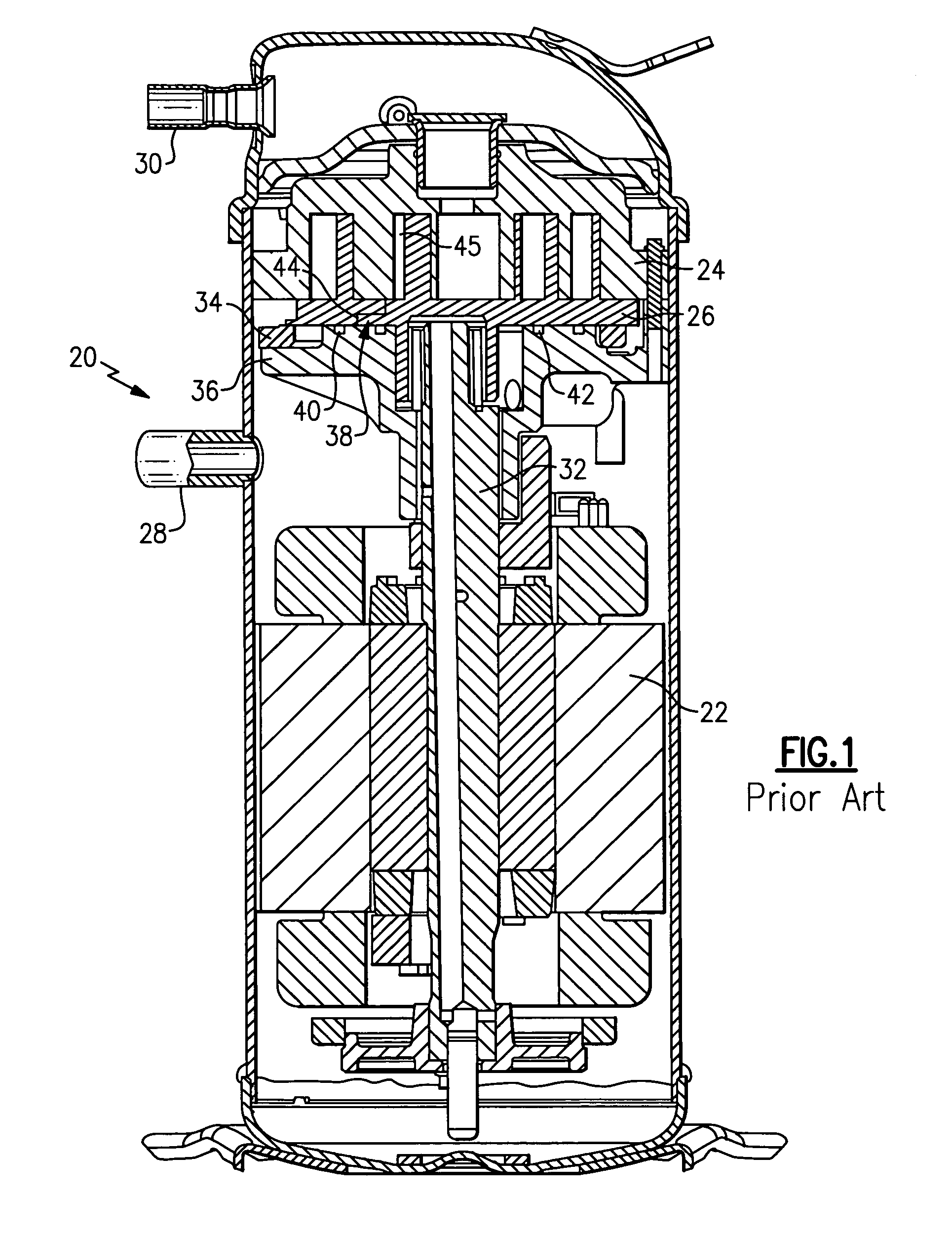
[0013]A scroll compressor 20 is illustrated in FIG. 1. As known, a motor 22 is provided to drive a shaft 32. An orbiting scroll member 26 is driven by the shaft 32 to orbit relative to a non-orbiting scroll member 24. An Oldham coupling 34 converts the rotation of the shaft 32 to orbiting movement of the orbiting scroll member 26.

[0014]As also known, a suction port 28 allows refrigerant to enter the compressor 20, and a discharge port 30 delivers compressed refrigerant to a downstream user, such as a condenser in a refrigeration system.

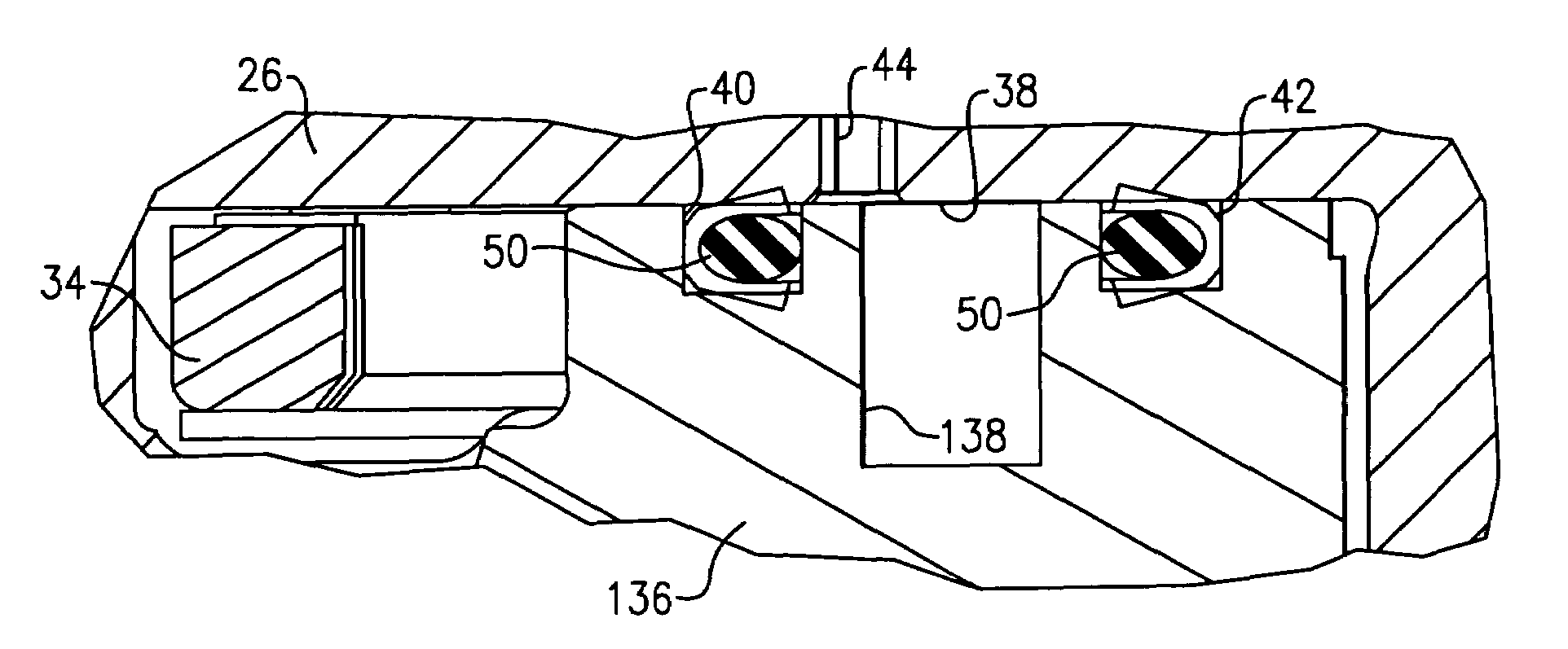
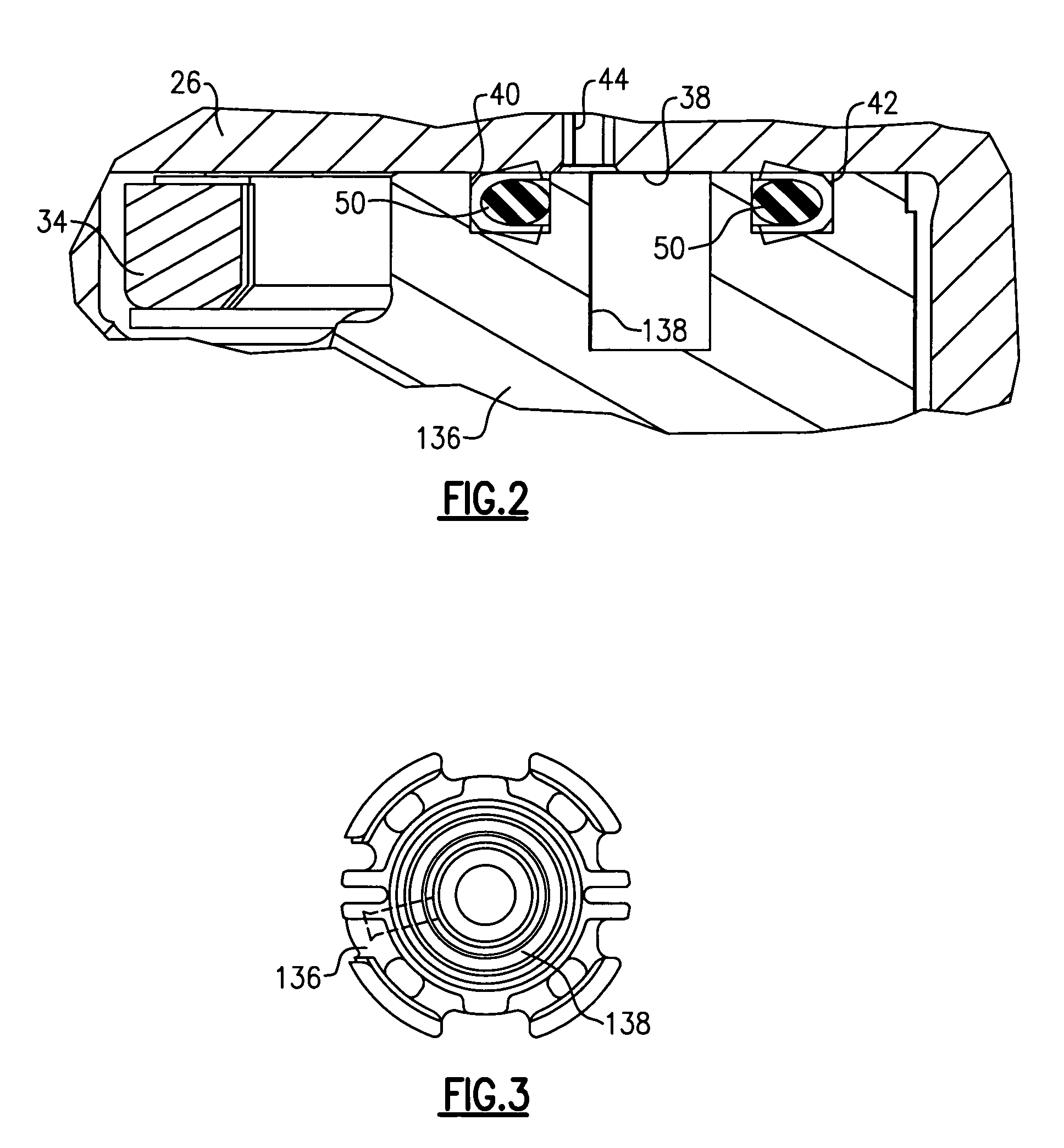
[0015]A crank case 36 supports the orbiting scroll member 26. A back pressure chamber 38 is defined between an upper face of the crank case 36 and a rear face of the base of the orbiting scroll 26. While the back pressure chamber 38 is shown behind the orbiting scroll 26, it is also known to position a back pressure chamber behind the non-orbiting scroll, and this invention would extend to such a compressor.

[0016]Seal grooves 40 and 42 are formed in t...


PUM


Abstract

A scroll compressor is provided with a cavity in its back pressure chamber to increase a volume of the back pressure chamber. In this manner, at start-up, the back pressure chamber will not be effective to bias the two scroll members together until this enlarged volume is filled with a compressed refrigerant. This reduces the load on the electric motor at start-up.

Description

BACKGROUND OF THE INVENTION[0001]This application relates to a scroll compressor, wherein a back pressure chamber is provided with a large cavity to reduce the start-up load on the motor. The large cavity must be filled with pressurized fluid as the compressor starts up before the scroll members can move into engagement with each other.[0002]Scroll compressors have become widely utilized in refrigerant compression applications. In a typical scroll compressor, a first scroll member includes a base with a generally spiral wrap extending from the base. A second scroll member also has a base and a generally spiral wrap extending from its base. The two wraps interfit to define compression chambers. One of the two scroll members is caused to orbit relative to the other, and as they orbit, the size of the compression chambers is decreased, compressing an entrapped refrigerant.[0003]A separating force is created by the compressed refrigerant that tends to push the two scroll members away fr...

Claims


Application Information

Patent Timeline
Patent Type & Authority Patents(United States)
IPC IPC(8): F04C18/00F04C2/00
CPCF04C27/005F04C28/06
Inventor HAHN, GREGORY W.
Owner DANFOSS (TIANJIN) CO LTD
Why Eureka
Try Eureka