Slide structure of seat for vehicle

a technology for sliding structures and vehicles, applied in the direction of movable seats, machine supports, roofs, etc., can solve the problems of deteriorating smooth sliding function, movable and stationary rails,

Inactive Publication Date: 2014-10-14
NHK SPRING CO LTD
View PDF11 Cites 27 Cited by
  • Summary
  • Abstract
  • Description
  • Claims
  • Application Information

AI Technical Summary

Benefits of technology

[0012]The object of the present invention is to provide a slide structure of a seat for a vehicle which is capable of always securing a smooth sliding function, no matter the position in the longitudinal direction of the vehicle the seat for the vehicle is located.
[0014]In the present invention, the torsion generated on the movable rail can be restricted, and thus, the smooth sliding function of the movable rail relative to the stationary rail can be secured by adjusting the positional relationship between a parallelogram link mechanism and the movable rail in the widthwise direction of the vehicle in such a way that the shear load acting on the movable rail with a C-shaped cross-section through a link of the parallelogram link mechanism passes through the shear center of the movable rail utilizing the fact that the shear center never fails to be located at the backside (the side opposite to the one which the C-shaped cross-section is opened) in case of a structure with a C-shaped or U-shaped cross-section.
[0015]More specifically, when the movable inner rail is brought into an overhanging situation due to a case where the cushion seat is positioned to be in the most frontward position, so that the front end of the movable inner rail protrudes forward from the front end of the stationary outer rail, or a case where the cushion seat is positioned to be in the most rearward position, so that the rear end of the movable inner rail protrudes rearward from the rear end of the stationary outer rail, by adjusting the relative positional relationship in the widthwise direction between the movable inner rail and the front link or the rear link by a means for adjusting the widthwise position in such a way that the shear load transmitted from the front link or the rear link passes through the shear center located to be at the inward side in the widthwise direction of the side surface portion of the movable inner rail, the generation of the torsional moment on the movable inner rail can be restricted, even if the shear load is exerted on the movable inner rail via the front link or the rear link, whereby the generation of the locking of the slide in the longitudinal direction of the movable inner rail relative to the stationary outer rail can be restricted, so much so that the generation of a strange sound or noise can be prevented when the movable inner rail is forcibly slid relative to the stationary outer rail and, as a result, the smooth slide function can be always secured, no matter in which longitudinal position the movable inner rail is located relative to the stationary outer rail.

Problems solved by technology

However, such a slide structure raised the following technical problems, due to the fact that the shear load in the vertical direction is exerted on the movable rail via the front and rear links of the parallelogram link mechanism.
That is, a smooth sliding function can be deteriorated in such a way that the movable and stationary rails can worsen to such a degree that they are brought into a locking situation, or a strange sound or a noise is generated upon a forcible sliding action, depending on the positional relationship between the movable and stationary rails.

Method used


Image

  • Slide structure of seat for vehicle
  • Slide structure of seat for vehicle
  • Slide structure of seat for vehicle

Examples


first embodiment

[0052]the slide structure of the present invention will be described in detail with reference to the drawings as an example.

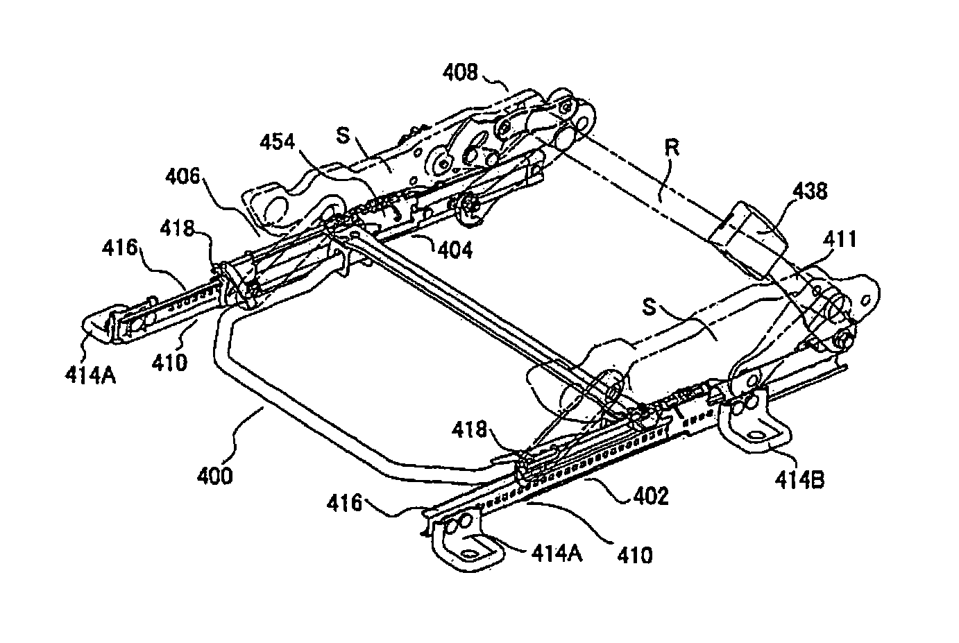
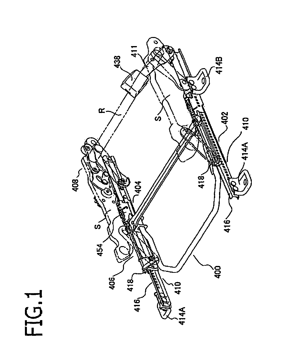
[0053]As shown in FIG. 1, a slide structure 400 of the seat for the vehicle generally comprises a mechanism 402 for adjusting the longitudinal position of the seat for the vehicle, a mechanism 404 for positioning the vehicle seat in the longitudinal direction, a mechanism 406 for adjusting the vertical position of the seat for the vehicle, and a mechanism 408 for positioning the vehicle seat in the vertical direction.

[0054]The vehicle seat comprises a pair of side frames S each extending in the longitudinal direction of the vehicle, front and rear pipes F, R each connecting the pair of side frames, a seat cushion fixed on the vehicle (not shown), and a seat back (not shown) mounted on the seat cushion via a recliner (not shown) so as to be reclined relative to the seat cushion. Since the slide structure 400 of the seat for the vehicle is provided on the side fr...

second embodiment

[0114]Further, in the second embodiment, the positioning collar 64 was adopted as a means for adjusting the position in the widthwise direction between the movable outer rail 418 and the lifter link, however, the positioning collar 64 may be omitted by providing a protruding flange on the peripheral surface of the link pin 50 to weld the link pin 50 to the movable outer rail 418, with respect to the front link at the inner side, and the front and rear links at the outer side, although the positioning collar 64 is necessary with respect to the rear link at the inner side due to the fact that the reinforcing bracket 51 is required for reinforcing the movable outer rail 418 because of the provision of the belt anchor.


PUM


Abstract

A slide structure of a seat for a vehicle positions a cushion seat in the longitudinal direction of the vehicle has a stationary outer rail which extends in the longitudinal direction of the vehicle and a substantially C-shaped cross section, an open portion which is oriented to be inner in the widthwise direction, and is disposed such that its cross section is elongate in the vertical direction, a movable inner rail which extends in the longitudinal direction of the vehicle and fits over the stationary outer rail so as to be slid relative to the stationary outer rail in the longitudinal direction and is fixed on the cushion seat and includes a substantially C-shaped cross section, an open portion of which is oriented to be outer in the widthwise direction, and is disposed in such a way that its side surface is elongate in the vertical direction.

Description

FIELD OF THE INVENTION[0001]The present invention relates to a slide structure of a seat for a vehicle and, particularly, relates to the slide structure of the seat for the vehicle which is capable of always securing a smooth sliding function, no matter in which position in the longitudinal direction of the vehicle the seat for the vehicle is located.BACKGROUND OF THE INVENTION[0002]The present inventor proposed in a patent publication 1 a slide structure of a seat for a vehicle including movable and stationary rails, each of which is disposed to be along a longitudinal direction of the vehicle and includes a C-shaped cross-section.[0003]The slide structure comprises a stationary rail which is fixed on a vehicle floor and extends in the longitudinal direction of the vehicle and a movable rail which fits over the stationary rail in the longitudinal direction so as to be slid on the stationary rail in the longitudinal direction, and the movable rail is connected to the cushion seat vi...

Claims


Application Information

Patent Timeline
Patent Type & Authority Patents(United States)
IPC IPC(8): F16M13/00B60N2/02B60N2/07B60N2/08B60N2/16B60N2/42
CPCB60N2/0715B60N2/167B60N2/0843B60N2/0881B60N2/4228B60N2/1615B60N2/0825B60N2/168B60N2/0747B60N2/1665
Inventor NONOMIYA, MASAAKI
Owner NHK SPRING CO LTD
Why Eureka
Try Eureka