Composite drain plug

a technology of drain plugs and composites, applied in the direction of washers, screws, threaded fasteners, etc., can solve the problems of high labor intensity, high cost, and inability to fully satisfy the approach of replacing an engine under warranty,

Inactive Publication Date: 2008-01-24
SKF USA INC
View PDF5 Cites 12 Cited by
  • Summary
  • Abstract
  • Description
  • Claims
  • Application Information

AI Technical Summary

Benefits of technology

[0012]A still further object is to provide a plug design which by reason of the type of materials used limits the torque which can be applied by the user.

Problems solved by technology

With the increased cost of automobile engines, and particularly in view of their incorporation into compact mechanisms which include front wheel drive assemblies and the like, replacement of an engine under warranty is not only highly expensive, but is also a highly labor-intensive operation.
However, with repeated use, such washer might be lost, scored or otherwise damaged, so such an approach has not been fully satisfactory.
Cost and lack of reliability are also drawbacks to the approach of separate sealing elements.
While there are some advantages to this approach, new automotive engines achieve constantly higher operating temperatures, at least transiently, and obtaining suitable plastic materials for sealing engine parts is difficult.
Under these conditions, resinous materials used as a part of the sealing system may have either been inadequate to withstand high temperatures, or more commonly, the resinous material undergoes cold flow and takes a compression set, thus compromising the residual compressive force needed to maintain a seal.
Thus, a part which is initially sealed in a highly fluid-tight manner might lose its seal with the passage of time.
Some such units may even lose substantial sealing effectiveness before leaving the place of manufacture.
Certain attempts have been made to provide electrometric seals for these applications, but the use of separate elastomeric washers and the like has created problems with assembly, and also has created problems of controlling the degree of compressive force which is applied as the parts are fastened together during assembly.
While insufficient forces create a risk of leakage, excessive forces have been known to damage the elastomeric or plastomeric seal components and thus create a risk of leakage in the short or long term.

Method used


Image

  • Composite drain plug
  • Composite drain plug
  • Composite drain plug

Examples


Embodiment Construction

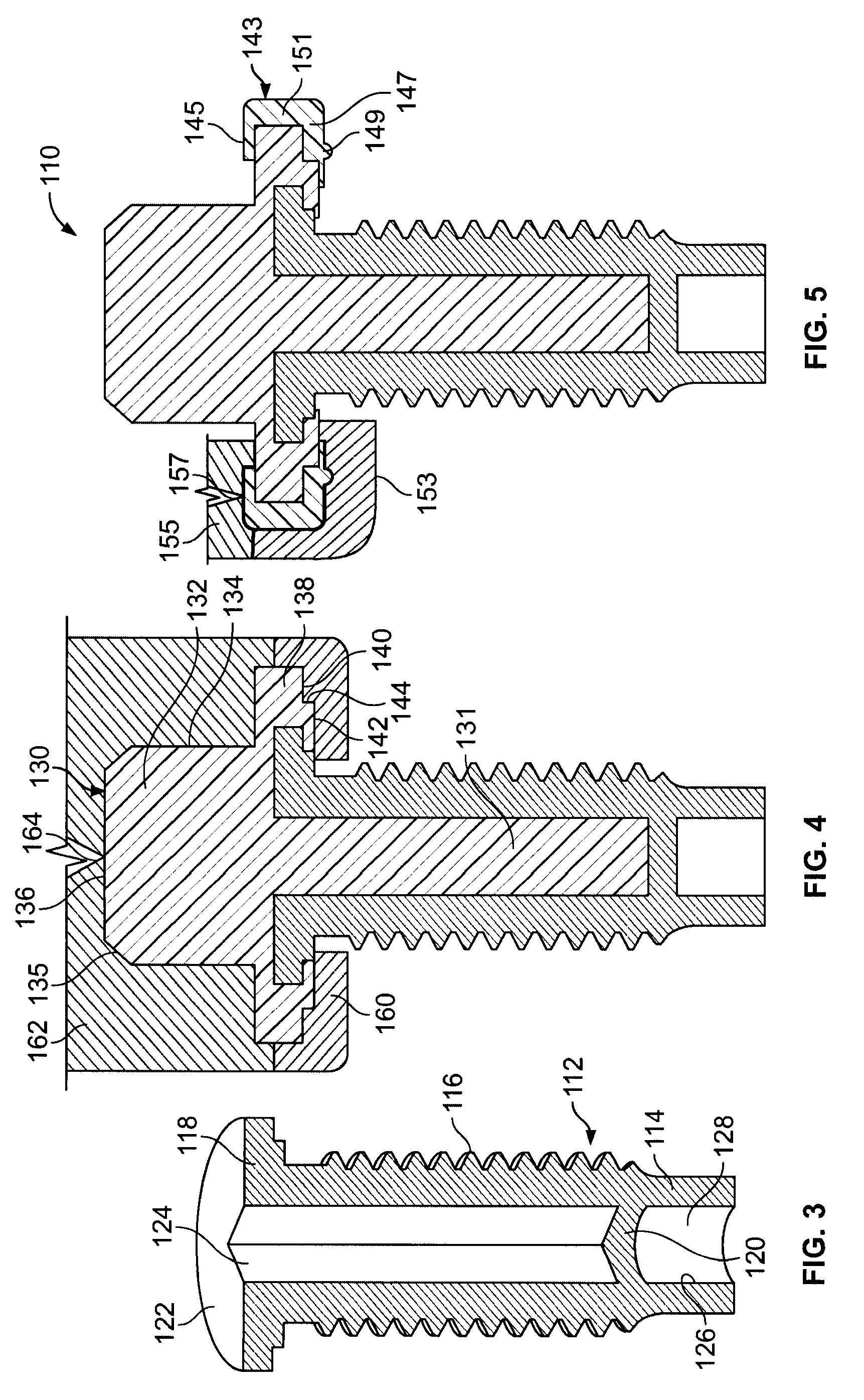
[0026]Although it will be understood there are various ways of making some of the products described and changes can be made to the form of invention which will now be described, a pair of inventive, slightly different designs will now be illustrated.

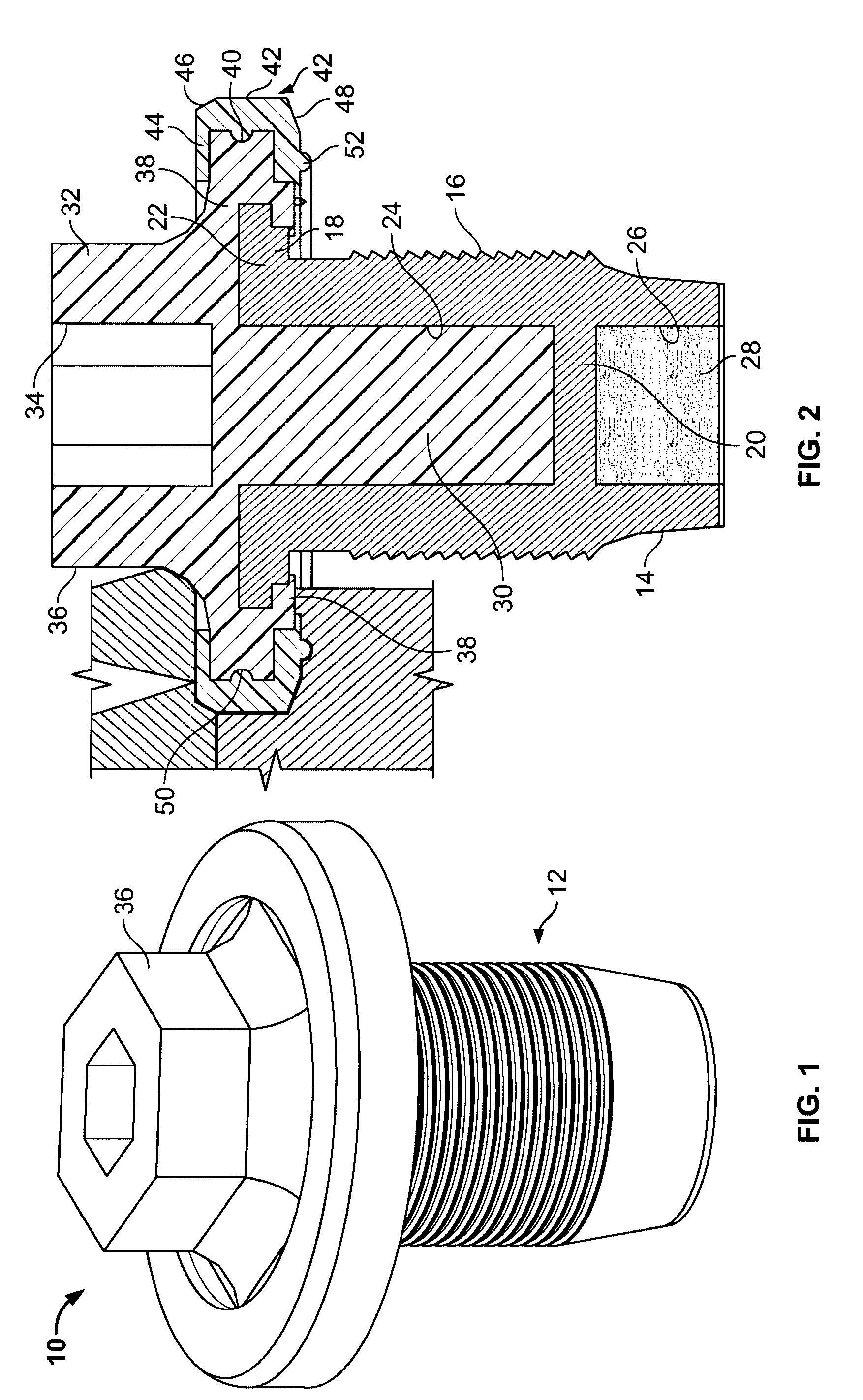
[0027]Referring now to FIGS. 1 and 2, there is shown one form of drain plug or drain bolt assembly generally designated 10.

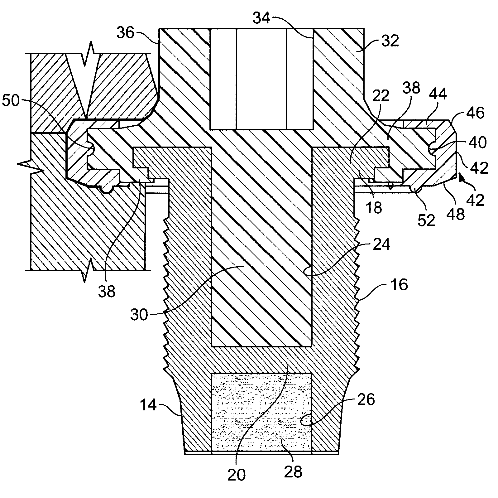
[0028]The first component of this assembly 10 is a metal sleeve generally designated 12 as shown to include a lower, thread-free portion 14, an exterior threaded portion 16, and a flange portion 18. The sleeve includes a bottom wall 20 and a flat top portion 22. There is defined an elongated interior wall 24, and a shortened interior wall portion 26. These walls 20, 26 leave a pocket 28 which optionally contains a magnet or a magnetic material to attract small metal filings from the engine itself. The elongated interior wall 24 and the top flange 22 define most of the volume of the engineered thermoplastic core 30, ...


PUM


Abstract

A composite drain plug for an automobile engine. The drain plug is made up of a hollow metal sleeve that is flanged at one end and closed at the other end. There is a core portion filling the hollow sleeve and having a head portion and a stub flange adjacent the flanged end of the sleeve. A circumferential sealing bead is bonded to the stub flange. The core portion is a glass-filled polymer and the sealing bead is made from a material which includes a cross-linked elastomer dispersed in a thermoplastic carrier.

Description

BACKGROUND OF THE INVENTION[0001]The present invention relates generally to automotive-related specialty products, and more particularly, to a composite drain plug for use in the oil pan of an automotive engine, or for use in another application wherein a fluid is sealed within an enclosed area from which it is desired to permit periodic draining and replenishment of fluid requiring plug removal. When used as a drain plug for an automotive engine oil pan, the one-piece unit of the invention comprises a plug body and a seal arrangement having a number of design features particularly adapted to solve persistent problems in the area of drain plug sealing.[0002]By way of background, in the automotive industry, literally millions of automotive engines are produced every year. Each of these engines is designed to operate for an extremely extended life, and according to current practice in the automotive industry, such engines are designed to operate with an absolute minimum of maintenance...

Claims


Application Information

Patent Timeline
Patent Type & Authority Applications(United States)
IPC IPC(8): F16B35/02F16K31/44
CPCF01M2011/0416F01M11/0408Y10S411/903Y10S411/901
Inventor DENTON, DENNIS NELSONSOCHACKI, THOMAS
Owner SKF USA INC
Why Eureka
Try Eureka