Decoupler with one-way clutch and fail-safe system

a one-way clutch and decoupler technology, applied in the direction of couplings, belts/chains/gearrings, portable lifting, etc., can solve the problems of increasing the weight and cost of the decoupler, requiring more complex production processes, and affecting the service life of the decoupler, so as to achieve low cost, good durability, and reduce the effect of strength materials

Active Publication Date: 2018-04-19
ZEN S A IND METALURGICA
View PDF0 Cites 11 Cited by
  • Summary
  • Abstract
  • Description
  • Claims
  • Application Information

AI Technical Summary

Benefits of technology

[0011]A first object of the invention is to provide a decoupler that performs both free wheel and vibration damping function...

Problems solved by technology

This friction involves high levels of compression and may cause great wear on the components of the clutch, and in particular on the pulley.
These requirements increase the weight and cost of the decoupler, and require more complex production processes.
However, the larger is the spring, the greater is its strength for the required level of torque for the application.
However, the dimensions of the torsion spring are limited by the reduced internal space of the clutch spring.
Another drawback found in the state of the art of decouplers, such as the previous documents mentioned here, is the occurrence of leakage of the grease used to lubricate the clutch spring, torsion spring and other parts, due to centrifugal force generated when the decoupler is in operation.
This contact zone between the axle hub and pulley is not completely leakage-free Seals may be used to reduce leakage between these parts, but t...

Method used


Image

  • Decoupler with one-way clutch and fail-safe system
  • Decoupler with one-way clutch and fail-safe system
  • Decoupler with one-way clutch and fail-safe system

Examples


Embodiment Construction

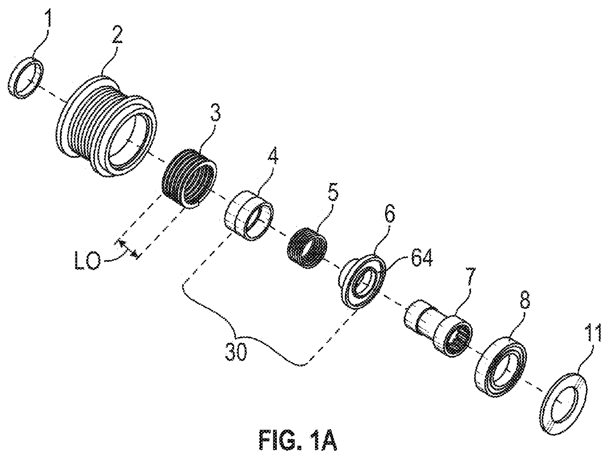
[0066]The present invention relates to a decoupler with free wheel system and vibration damping mechanism, as shown in FIGS. 1 to 15, which can be used for different types of mechanical devices such as the coupling between pulleys and alternators in automotive vehicles.

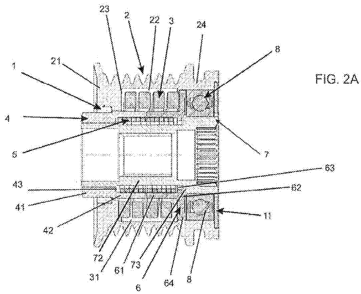
[0067]As can be seen most clearly in FIGS. 1A and 2A, the decoupler comprises a shaft 7 to be driven, an axle hub 30 disposed around a driven shaft 7, a pulley 2 arranged externally to the axle hub 30 responsible for driving the shaft, at least one mechanical element for journaling and centering between the shaft 7 and the pulley 2, a torsion spring 3 and a clutch spring 5. The torsion spring 3 is disposed between the outer race of the axle hub 30 and the inner race of the pulley 2 with a first end operatively attachable to the pulley 2 and a second end operably attachable to the axle hub 30.

[0068]The clutch spring 5 is disposed radially inward of the torsion spring 3 and is frictionally attachable to the axle hub 30 ...


PUM


Abstract

The present invention relates to a decoupler with free wheel system and comprising a vibration damping pulley, a shaft actionable by the pulley, hub pieces having a first hub piece and a second hub piece, hub pieces being mounted between the inner race of the pulley and the outer surface of the shaft, at least one journal element between the shaft and pulley, along with a torsion spring, and a clutch spring, with the first hub piece being mounted on the shaft and the second hub piece being mounted around the shaft and can rotate relative to it, the torsion spring being disposed between the outer race of the hub pieces and the inner race of pulley, having a first end operatively attachable to the pulley and a second end operatively attachable to the second hub piece and the clutch spring being disposed internally in relation to the torsion spring and which is frictionally engaged with the hub pieces for transmission of torque to the shaft.

Description

CROSS-REFERENCE TO RELATED APPLICATIONS[0001]This application is a continuation-in-part of U.S. application Ser. No. 15 / 470,620 having a filing date of Mar. 27, 2017, which is a continuation of U.S. application Ser. No. 14 / 238,787 having a filing date of 13 Feb. 2014, which is a national stage application under 35 U.S.C. 371 of PCT Application No. PCT / BR2013 / 000349 having an international filing date of 9 Sep. 2013, which designated the United States, and wherein the PCT application claimed the benefit of Brazil Application No. BR102012022803-3 filed on 10 Sep. 2012, the entire disclosure of each application being incorporated herein by reference.FIELD OF THE INVENTION[0002]The present invention relates to a decoupler system with free wheel operation and a vibration damping mechanism that can be applied to mechanical connections, such as alternators in vehicles. The decoupler mechanism according to the invention has a fail-safe system and can also be configured to operate as a one-w...

Claims


Application Information

Patent Timeline
IPC IPC(8): F16H55/36F16D41/20F16D3/12F16D3/72
CPCF16H55/36F16D41/206F16H2055/366F16D3/12F16D3/72F16D2300/22
Inventor CANTO MICHELOTTI, ALVARO
Owner ZEN S A IND METALURGICA
Why Eureka
Try Eureka