Tip shield with gripping surfaces and guard features

a technology of gripping surface and protective shield, which is applied in the direction of guide needles, needles, catheters, etc., can solve the problems of rotational force, painful, disruptive, undesirable, etc., and achieve the effect of preventing the “over the bevel” condition, preventing the risk of encountering, and choking up the grip

Active Publication Date: 2014-10-14
BECTON DICKINSON & CO
View PDF51 Cites 12 Cited by
  • Summary
  • Abstract
  • Description
  • Claims
  • Application Information

AI Technical Summary

Benefits of technology

[0010]In order to overcome the limitations discussed above, the present invention relates to a new gripping surface that may be incorporated into a current catheter assembly. The new gripping surface allows a user to use a “choked up” grip without the risk of encountering an “over the bevel” condition. As is known in the art, traditional gripping surfaces are provided to aid a user in griping and controlling the catheter assembly during insertion of the catheter. The gripping surface of the current invention is designed to be used alone or in conjunction with current, traditional gripping surfaces and is designed to allow a “choked up” grip while preventing the “over the bevel” condition.
[0011]Unlike traditional gripping surfaces commonly located on an outer surface of the needle hub of the catheter assembly, the present invention is located on an outer surface of the needle shield, thereby providing a gripping surface closer to the catheter and introducer needle tip portions of the catheter assembly. As such, the current invention provides an optional gripping surface for safely repositioning a user's fingers and thumb nearer the catheter and introducer needle without causing an “over the bevel” condition. Accordingly, if a user repositions their grip to the gripping surface of the needle shield, the new gripping surface will provide the user with improved control and balance over the prior art.
[0013]The catheter assembly is configured such that a wing portion of the needle hub overlaps a portion of the needle shield such that the wing portion of the needle hub abuts the first gripping surface. The wing portion and the first gripping surface provide a contact surface for accommodating a second portion of the user's thumb. Thus, the user simultaneously contacts the needle shield and the needle hub. This simultaneous contact of the user's thumb serves as a link or bridge between the needle shield and the needle hub thereby preventing a premature separation of the components during insertion of the catheter.
[0014]A second gripping surface is also provided to accommodate the contours of a user's first non-opposable digit, such as the user's index finger. The second gripping surface is sized and positioned to allow various positioning of the user's index finger. For example, the second gripping surface permits a user's index finger to be positioned opposite the user's thumb thereby forming a symmetrical, balanced grip. With the user's index finger in a balanced, symmetrical position, the design of the second gripping surface ensures that a first portion of the user's index finger contacts the second gripping surface, while a second portion of the user's index finger contacts a wing portion of the needle hub. As such, the user's index finger serves to link together the needle shield and the needle hub during insertion, thereby preventing premature separation, or an “over the bevel” condition.
[0015]Additionally, a user's index finger may grip a portion of the second gripping surface in an asymmetrical position closer to the catheter adapter thereby forming an imbalanced, asymmetrical grip. To balance this imbalanced, asymmetrical grip, a user's second non-opposable finger, such as a middle finger, is positioned on a gripping surface of the needle hub. The addition of the middle finger balances the catheter assembly and overcomes any undesirable rotational force created by the imbalanced, asymmetrical grip. The positioning and combined contact of the user's thumb, index finger, and middle finger serve to link together the needle shield and needle hub of the catheter assembly. As such an “over the bevel” condition or premature separation of the needle shield and the needle hub is prevented.

Problems solved by technology

As such, this “over the bevel” condition is painful, disruptive, and undesirable during insertion of the needle.
However, the imbalanced, asymmetrical grip results in a rotational force 90 that is incompatible with insertion procedures for the catheter 48.

Method used


Image

  • Tip shield with gripping surfaces and guard features
  • Tip shield with gripping surfaces and guard features
  • Tip shield with gripping surfaces and guard features

Examples


Embodiment Construction

[0025]The presently preferred embodiments of the present invention will be best understood by reference to the drawings, wherein like reference numbers indicate identical or functionally similar elements. It will be readily understood that the components of the present invention, as generally described and illustrated in the figures herein, could be arranged and designed in a wide variety of different configurations. Thus, the following more detailed description, as represented in the figures, is not intended to limit the scope of the invention as claimed, but is merely representative of presently preferred embodiments of the invention.

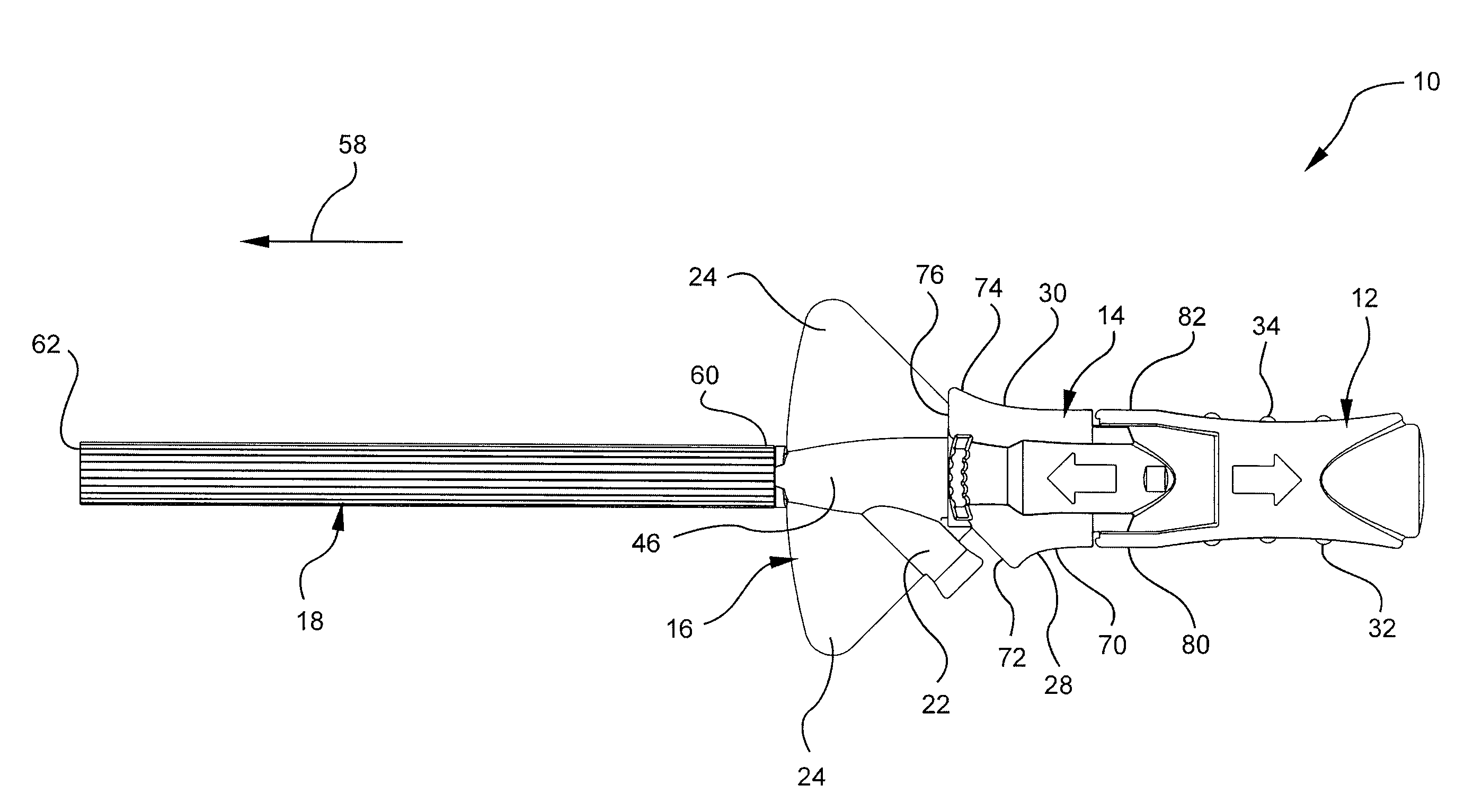
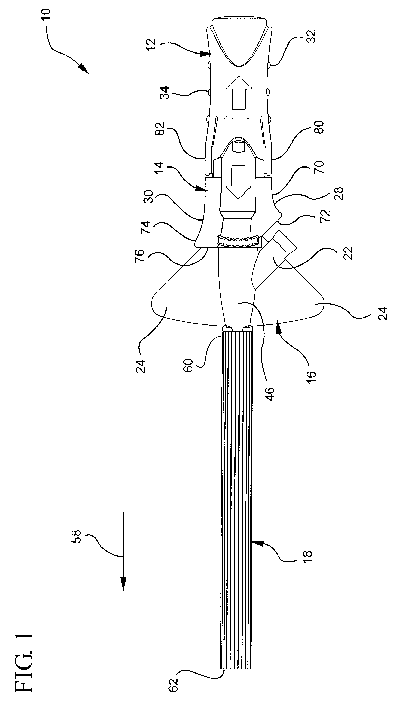
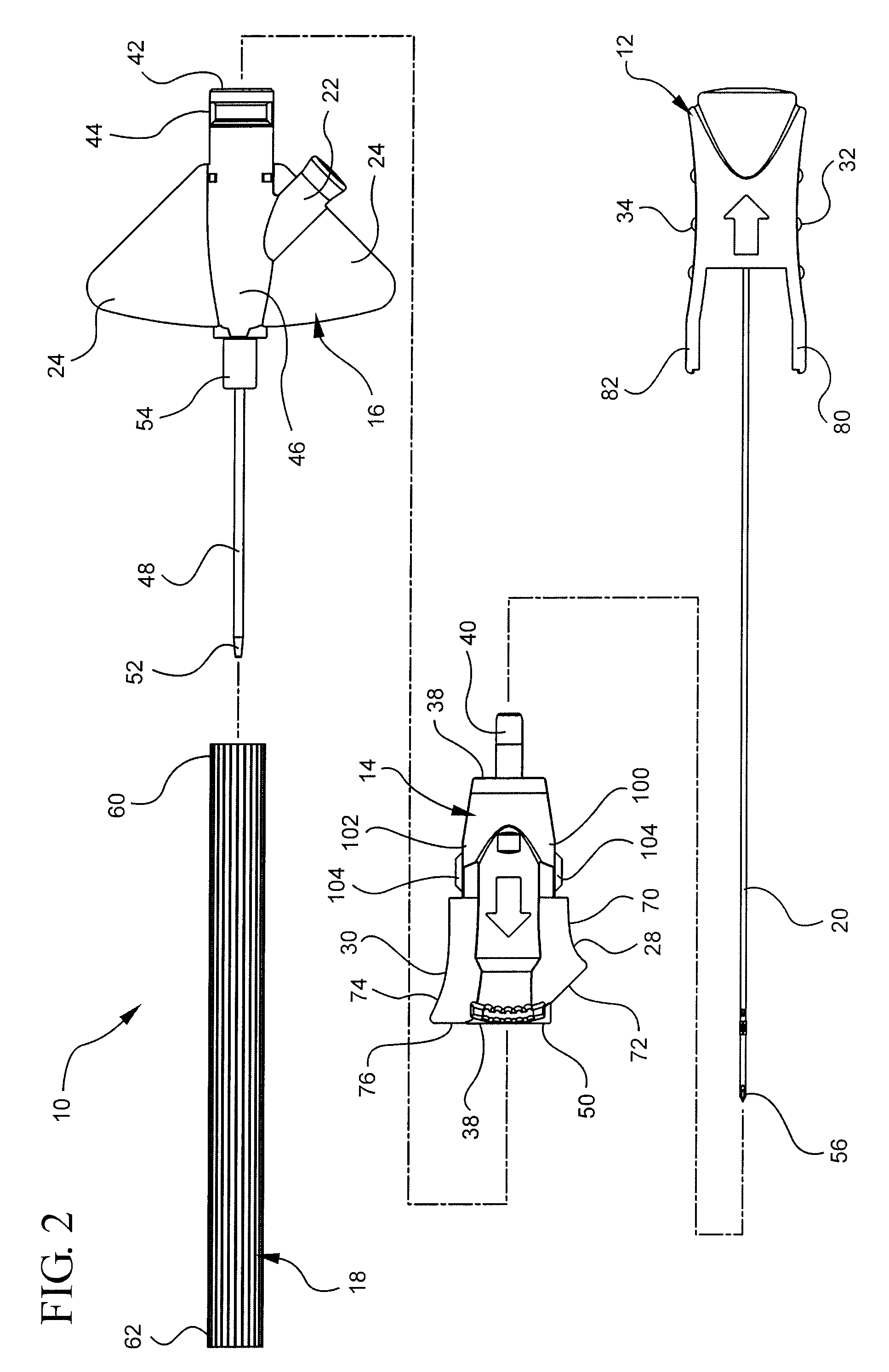
[0026]Referring now to FIGS. 1 and 2, a catheter assembly 10 is illustrated including a needle hub 12, a needle shield 14, a catheter adapter 16, an introducer needle 20, and a needle sheath 18. Each of the components 12, 14, 16, 20 and 18 of the catheter assembly 10 is configured so as to cooperate as an integrated apparatus. As more clearly illustra...


PUM


Abstract

An asymmetrical gripping surface is incorporated into a needle shield of an intravenous catheter assembly. The asymmetrical gripping surface provides a gripping position nearer the catheter adapter, catheter and needle tip for improved balance and control of the catheter assembly during insertion of the catheter. Additionally, the asymmetrical gripping surfaces include a guard feature to prevent a user's unintended contact with various components of the catheter assembly whereby the contact may result in an undesirable “over the bevel” condition.

Description

RELATED APPLICATIONS[0001]This application claims the benefit of U.S. Provisional Application No. 61 / 016,157, filed Dec. 21, 2007, entitled TIP SHIELD WITH GRIPPING SURFACES AND GUARD FEATURES, which is incorporated herein by reference.BACKGROUND OF THE INVENTION[0002]The present invention relates to infusion devices, specifically to over-the-needle peripheral intravenous (IV) catheters. Specifically, the invention relates to peripheral IV catheters with a protective needle shield having gripping surfaces to allow a user to hold the device nearer the catheter and needle tip for increased stability and control during insertion. Catheters are widely used throughout the medical community for a wide range of procedures and treatments.[0003]Catheters are commonly used for a variety of infusion therapies. Catheters are used for infusing fluid, such as normal saline solution, various medicaments, and total parenteral nutrition, into a patient, withdrawing blood from a patient, or monitorin...

Claims


Application Information

Patent Timeline
Patent Type & Authority Patents(United States)
IPC IPC(8): A61M5/178A61M5/32A61M25/06
CPCA61M25/0606A61M25/0618A61M25/0637A61M5/3202
Inventor BURKHOLZ, JONATHAN KARLISAACSON, S. RAYO'BRYAN, JEFFREY C.WANG, AARONPOWELL, WADE A.
Owner BECTON DICKINSON & CO
Why Eureka
Try Eureka