

Tongue cleaning device
a tongue cleaning and tongue technology, applied in the field of tongue cleaning devices, can solve the problem of a substantial portion of bacteria staying in the tongu
- Summary
- Abstract
- Description
- Claims
- Application Information
AI Technical Summary
Benefits of technology
Problems solved by technology
Method used
Image

Examples
first embodiment
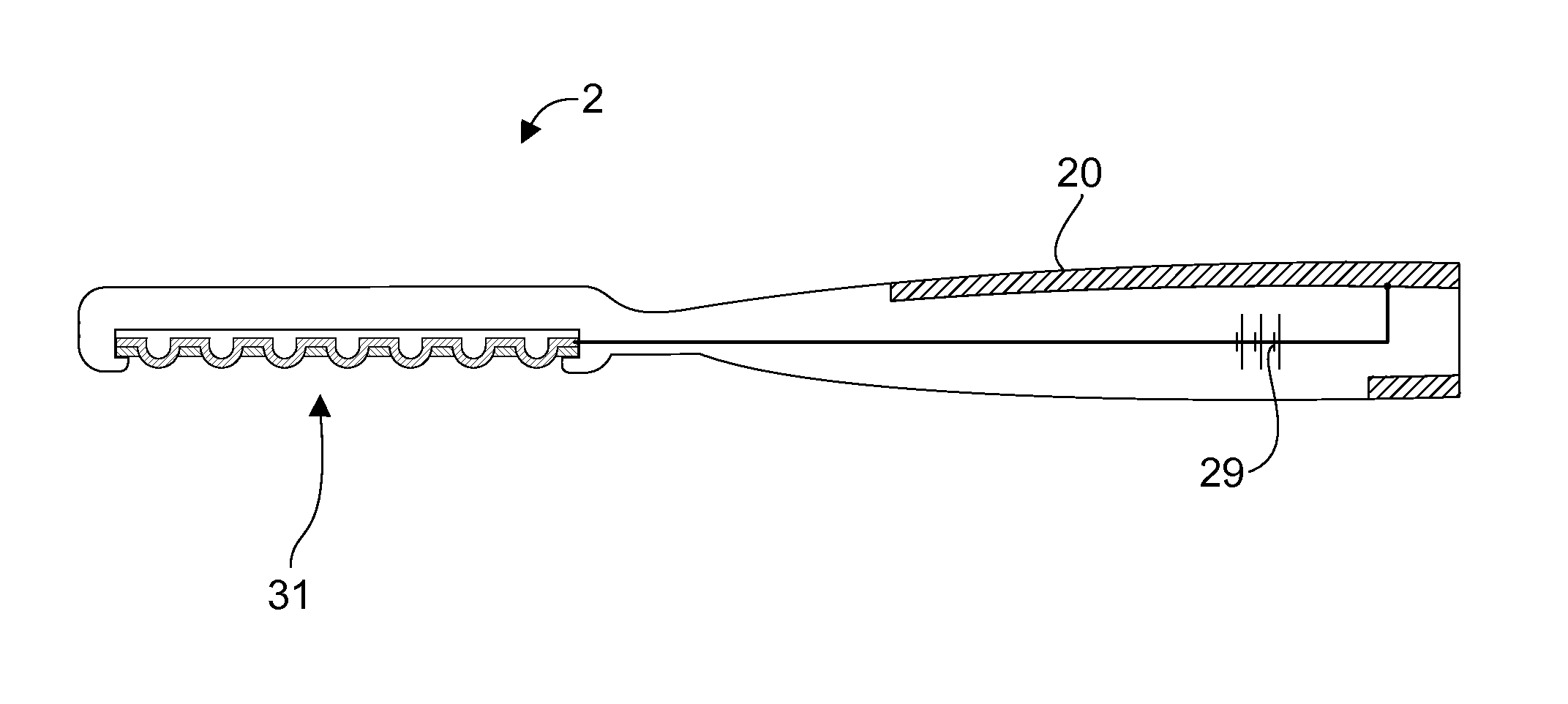
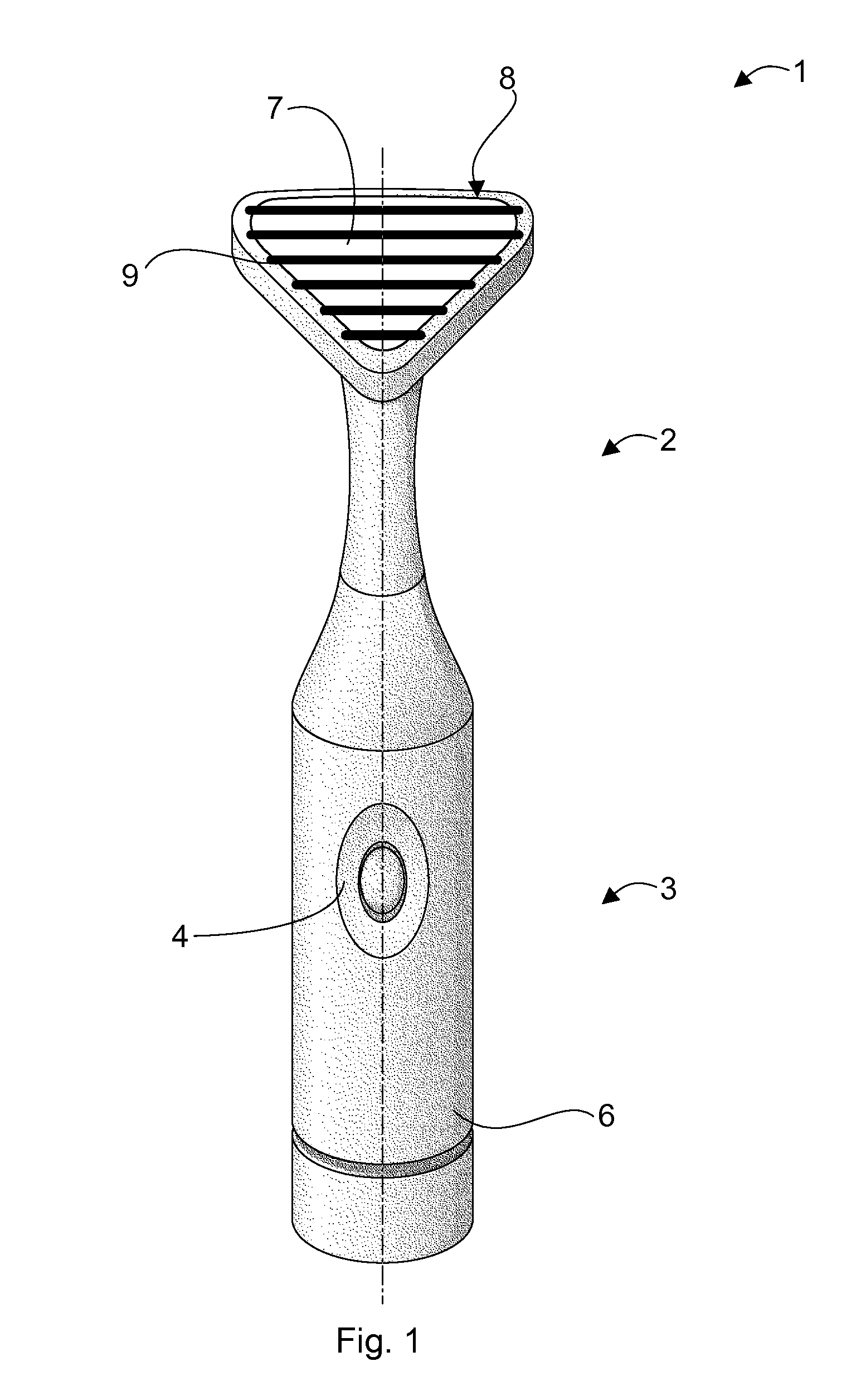
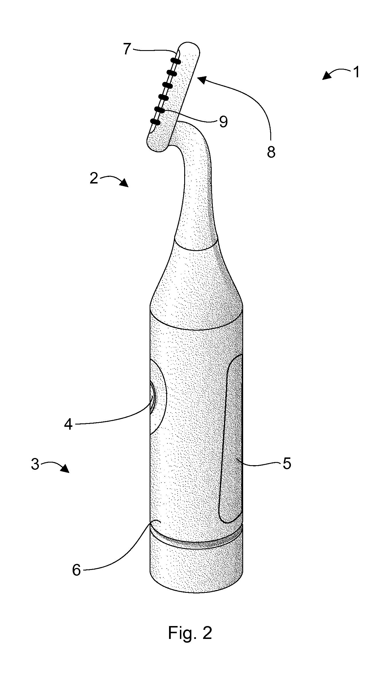
[0052]FIGS. 1 and 2 show a first exemplary embodiment of a tongue cleaning device 1. The tongue cleaning device 1 comprises a head portion 2 and a handle portion 3. In the depicted first embodiment, the head portion 2 and the handle portion 3 form an integral device, but the head portion 2 may be arranged as a detachable part to enable easy replacement of the head portion 2. The handle portion 3 comprises an energy source, for example, a rechargeable battery, for providing a supply voltage for driving a current flow initiating the transport of anti-bacterial agents into the user's tongue in an operation state, as will be explained further below. The handle portion 3 further comprises an on / off-switch button 4 and a contact electrode 5 placed on the rear side of the cylindrical housing of the handle portion 3 for establishing a contact between the contact electrode 5 and a user's hand during operation. Here, the contact electrode 5 is formed integrally with a housing 6 of the handle ...
second embodiment
[0058]FIG. 3 shows an alternative second exemplary embodiment of a tongue cleaning device 1. The plane and non-structured tongue cleaning electrode 7 as well as the ribs 9 of the mechanical tongue cleaning section 8 shown in FIGS. 1 and 2 have been replaced by a single laterally extending tongue cleaning electrode 10. The tongue cleaning electrode 10 of this second embodiment not only provides the functionality of a tongue cleaning electrode, but simultaneously forms the mechanical tongue cleaning section 8. In order to fulfill both functionalities, the tongue cleaning electrode 10 has a structured surface formed by etching a set of perpendicularly arranged grooves 11 into the tongue cleaning electrode 10. By applying the grooves 11 into the tongue cleaning electrode 10 the surface of the tongue cleaning electrode 10 consists of a more or less regular structure of cleaning protrusions in the form of rhombi extending above the grounds of the grooves 11. The arrangement of rhombi on t...
third embodiment
[0061]In order not only to apply a current, but also to allow mechanical scrubbing of the tongue the electrode 12 of the third embodiment depicted in FIG. 4 is itself shaped as a rib extending above the housing 15 of the head portion 2. The rib 12 extends essentially perpendicular to the axis of symmetry of the cylindrical housing 6 of the handle portion 3. The rib spans almost entirely over the full widths of the spoon-shaped housing 15 of the head portion 2 of the device 1. The rib 12 is also slightly curved around a centre of curvature lying on the axis of symmetry of the device between the rib 12 and the lower part of the housing 6 of the handle portion 3.
[0062]In the fourth embodiment shows in FIG. 5, the single rib 12 of the third embodiment of FIG. 4 has been replaced by a multiple set of ribs, in the shown embodiment by three ribs 13. This arrangement enhances the effect of mechanical scrubbing the tongue. In contrast, the fifth embodiment shown in FIG. 6 has five small-size...
PUM
 Abstract
Description
Claims
Application Information