
Image signature extraction device

a technology of image signature and extraction device, which is applied in the field of system for extracting image signatures, can solve the problems of low discrimination capability of image signature (feature vector), low discrimination capability of image signature, so as to improve discrimination capability, discrimination capability is not lowered, and the correlation between local regions in image is high

Active Publication Date: 2014-10-14
NEC CORP
View PDF47 Cites 0 Cited by
  • Summary
  • Abstract
  • Description
  • Claims
  • Application Information

AI Technical Summary

Benefits of technology

Enhances the discrimination capability of image signatures for images with high local correlation and maintains robustness against frequency components and alteration processes.

Problems solved by technology

In contrast, if correlation between dimensions in a feature vector is large, as the amount of information held by the feature vector is small (redundancy is large), the discrimination capability is low.
As such, there is a first problem that discrimination capability of the image signature (feature vector) is low.
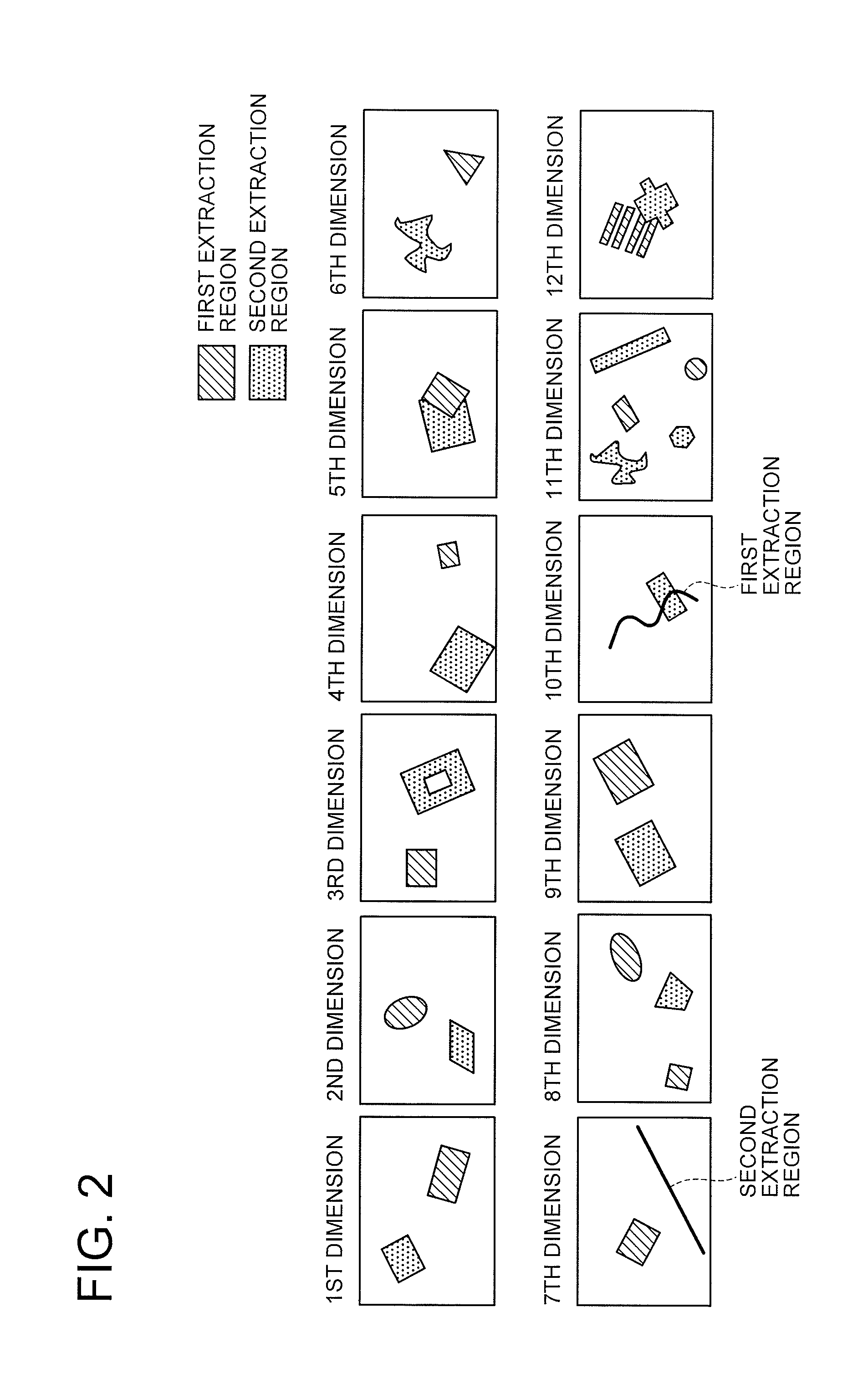
A second problem of the conventional image signature described in Patent Document 1 is that as the shapes of the regions of respective dimensions for calculating features (feature vector) are in the identical rectangle shape (including size and angle), there is a blind spot on frequencies where it is impossible to detect frequency components having a cycle which is the same as the length of a side of the rectangle or which is a fraction of the integer thereof.
Practically, as it is difficult to detect not only the components of the frequency nf0 (n=1, 2, 3, . . . ) but also a certain nearby frequency regions, even if signals do not concentrate on the above-described particular frequency, signal components of such a frequency band cannot be used, whereby the discrimination capability is lowered.
However, increasing the value of the frequency f0 means reducing the size of the region, leading to lowering of the robustness (a degree that a feature does not vary due to various alteration processes or noise) of the frequency.
As described above, when using the identical rectangle regions, it is extremely difficult to secure the robustness while increasing the discrimination capability.

Method used


Image

  • Image signature extraction device
  • Image signature extraction device
  • Image signature extraction device

Examples


first embodiment

[Operation of First Embodiment]

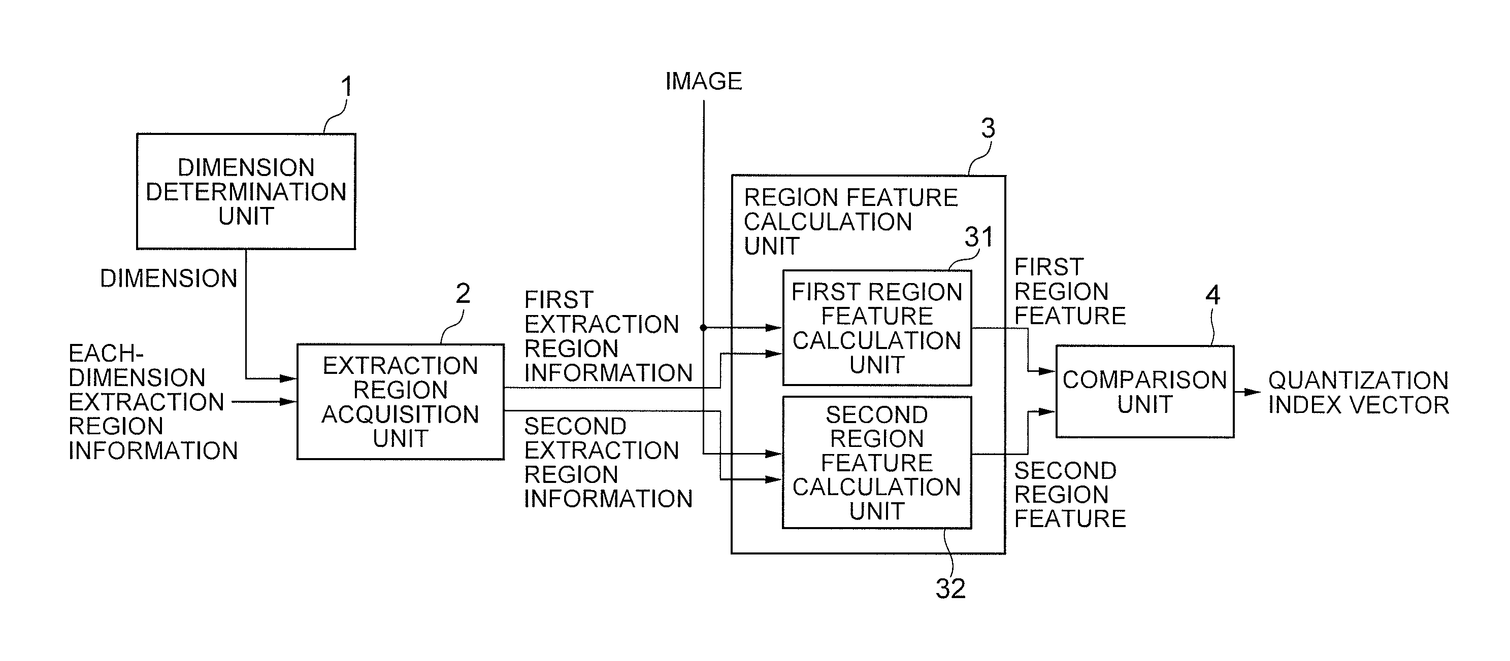
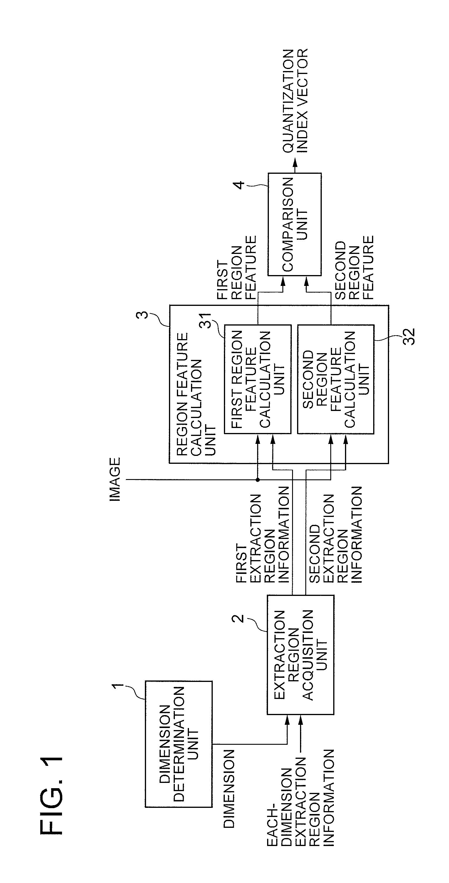
[0127]Next, operation of the image signature extraction device according to the first embodiment will be described with reference to the flowchart of FIG. 5. In the flowchart of FIG. 5, a dimension (number) of a feature vector is indicated by “n”, and there are N dimensions in total from 1 to N.

[0128]First, the dimension determination unit 1 determines a dimension 1 as the first dimension (n=1) for extracting a feature vector, and supplies it to the extraction region acquisition unit 2 (step A1).

[0129]Next, the extraction region acquisition unit 2 acquires information indicating a first extraction region and a second extraction region of the dimension n from each-dimension extraction region information supplied as an input, and supplies it to the region feature calculation unit 3 (step A2).

[0130]Then, the region feature calculation unit 3 calculates a first region feature and a second region feature of the dimension n from the image supplied as an inpu...

second embodiment

[Operation of Second Embodiment]

[0154]Next, operation of the image signature extraction device according to the second embodiment will be described with reference to the flowchart of FIG. 7. In the flowchart of FIG. 7, a dimension (number) of a feature vector is indicated by “n”, and there are N dimensions in total from 1 to N.

[0155]First, the dimension determination unit 1 determines a dimension 1 as the first dimension (n=1) for extracting a feature vector, and supplies it to the extraction region acquisition unit 2 (step B1).

[0156]Next, the extraction region acquisition unit 2 acquires information indicating a first extraction region and a second extraction region of the dimension n from each-dimension extraction region information supplied as an input, and supplies the information to the region feature representative value calculation unit 3 (step B2).

[0157]Then, the region feature representative value calculation unit 3 calculates a first region feature and a second region feat...

third embodiment

[Effect of Third Embodiment]

[0183]In addition to the advantageous effects of the first embodiment, the third embodiment has an advantageous effect that the discrimination capability which is a degree of discriminating different images can be further improved.

[0184]This is because as the region feature calculation methods are different among the dimensions (variable region feature calculation methods are used), correlation among dimensions can be small.

Fourth Embodiment

Configuration of Fourth Embodiment

[0185]Next, a fourth embodiment of the present invention will be described in detail with reference to the drawings.

[0186]Referring to FIG. 11, the configuration of the fourth embodiment of the present invention is different from that of the first embodiment shown in FIG. 1 in that a comparison method acquisition unit 6 is added, and the comparison unit 4 is replaced with a comparison unit 4B. As the other components are the same as those of the first embodiment, the explanation thereo...


PUM


Abstract

The image signature extraction device includes an extraction unit and a generation unit. The extraction unit extracts region features from respective sub-regions in an image in accordance with a plurality of pairs of sub-regions in the image, the pairs of sub-regions including at least one pair of sub-regions in which both a combination of shapes of two sub-regions of the pair and a relative position between the two sub-regions of the pair differ from those of at least one of other pairs of sub-regions, and being classified into a plurality of types based on a combination of shapes of two sub-regions and a relative position between the two sub-regions of each of the pairs. The generation unit generates an image signature to be used for identifying the image based on the extracted region features of the respective sub-regions.

Description

CROSS REFERENCE TO RELATED APPLICATION[0001]This application is a National Stage of International Application No. PCT / JP2010 / 002633 filed Apr. 12, 2010, claiming priority based on Japanese Patent Application No. 2009-97861, filed Apr. 14, 2009, the contents of all of which are incorporated herein by reference in their entirety.TECHNICAL FIELD[0002]The present invention relates to a system for extracting image signatures which are features for identifying (determining the identity of) images.BACKGROUND ART[0003]Image signatures are image features for identifying (determining the identity of) images. By comparing an image signature extracted from an image with an image signature extracted from another image, an identity scale (in general, referred to as similarity or distance) indicating a degree of the two images being identical can be calculated from a comparison result. Further, by comparing the calculated identity scale with a threshold, it is possible to determine whether or not ...

Claims


Application Information

Patent Timeline
Patent Type & Authority Patents(United States)
IPC IPC(8): G06K9/62G06K9/54H04H20/14G06V10/28G06V10/50
CPCG06K9/38G06K9/4642G06K9/50G06V10/28G06V10/50G06V10/421G06T7/00
Inventor OAMI, RYOMAIWAMOTO, KOTA
Owner NEC CORP
Learn More