
Work glove

a technology for working gloves and gloves, applied in gloves, protective garments, garments, etc., can solve the problems of deteriorating an operational efficiency, reducing workability, and less than optimal work gloves as solutions to overcome, so as to improve workability and wear resistance, improve workability, and improve the effect of friction coefficien

Inactive Publication Date: 2014-10-21
TOWA
View PDF34 Cites 15 Cited by
  • Summary
  • Abstract
  • Description
  • Claims
  • Application Information

AI Technical Summary

Benefits of technology

The invention provides a work glove that has enhanced mounting and dismounting properties, improved wear resistance, and workability. The glove base is formed of elastic material, and a fabric material is affixed to the outer surface of the glove base. The fabric material can be formed of cloth, knitted fabric, or meshed fabric, and has a higher friction coefficient than the fabric material. The fabric material can be affixed to the thumb, forefinger, or palm portion of the glove base for better fingertip workability. The fabric material can also be formed into a finger-bag or glove shape for better fingertip workability and wear resistance. A coating film is formed on the surface of the fabric material, which increases friction between the object and the work glove. The invention thus enhances workability and provides better grip while ensuring functions such as dielectric breakdown strength and water-proofing property.

Problems solved by technology

However, the above-mentioned conventional work glove has been developed for allowing a user to recognize a worn state of a coating layer, and the improvement of wear resistance is not taken into account and hence, the work glove is less than optimum as a solution to overcome the above-mentioned drawbacks fundamentally.
However, in such a method, the leather-made glove or the non-woven-fabric-made glove which is mounted on an elastic glove in an overlapping manner cannot sufficiently follow the shape of the elastic glove and hence, workability is extremely lowered thus remarkably deteriorating an operational efficiency.
Further, mounting and dismounting of the glove also become more cumbersome.

Method used


Image

  • Work glove
  • Work glove
  • Work glove

Examples


example 1

[0072][Example 1]

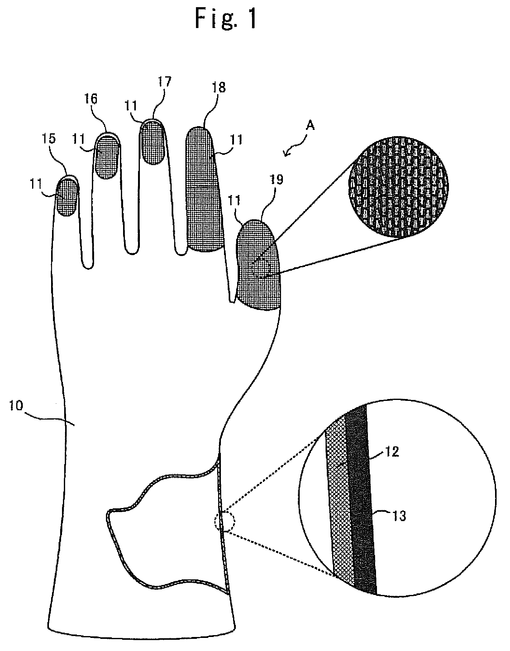
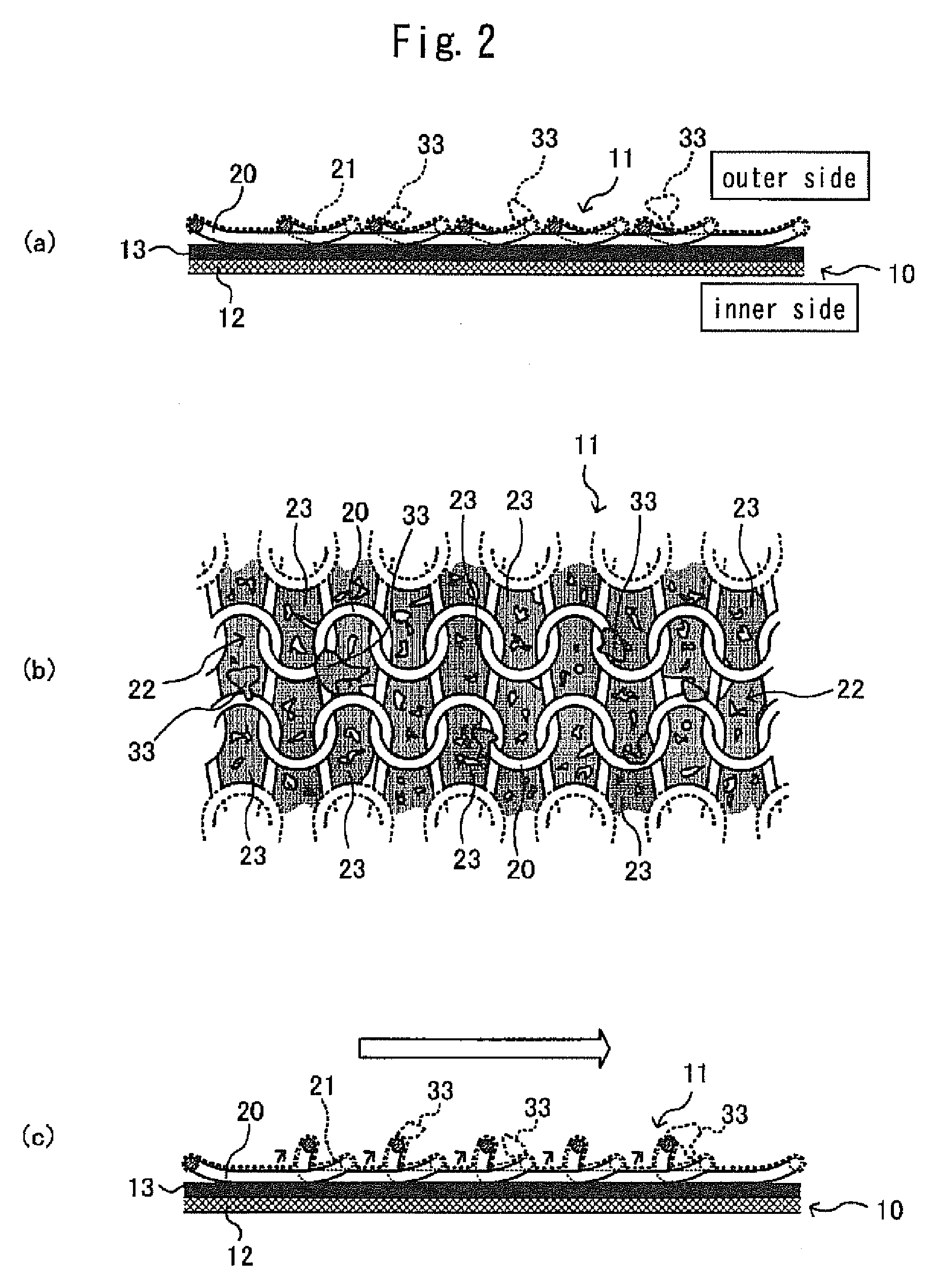
[0073]FIG. 1 is an explanatory view showing a palm side of a work glove A according to this embodiment. The work glove A includes: a glove base 10 made of natural rubber which is a resilient material; and a knitted fabric 11 which is a fabric material affixed to a surface of the glove base 10.

[0074]As shown in the drawing with a part broken away, the glove base 10 is constituted by forming a natural rubber layer 13 on a surface of a base glove 12 which is formed into a glove shape by knitting and weaving. A thickness of the natural rubber layer 13 is set to a thickness which substantially allows the work glove A to have dielectric breakdown strength.

[0075]On the other hand, the knitted fabric 11 is formed by knitting and weaving aramid fibers (spun yarns), and is affixed to an outer surface of a little finger portion 15, an outer surface of a ring finger portion 16, an outer surface of a middle finger portion 17, an outer surface of a forefinger portion 18 and an ou...

example 2

[0095][Example 2]

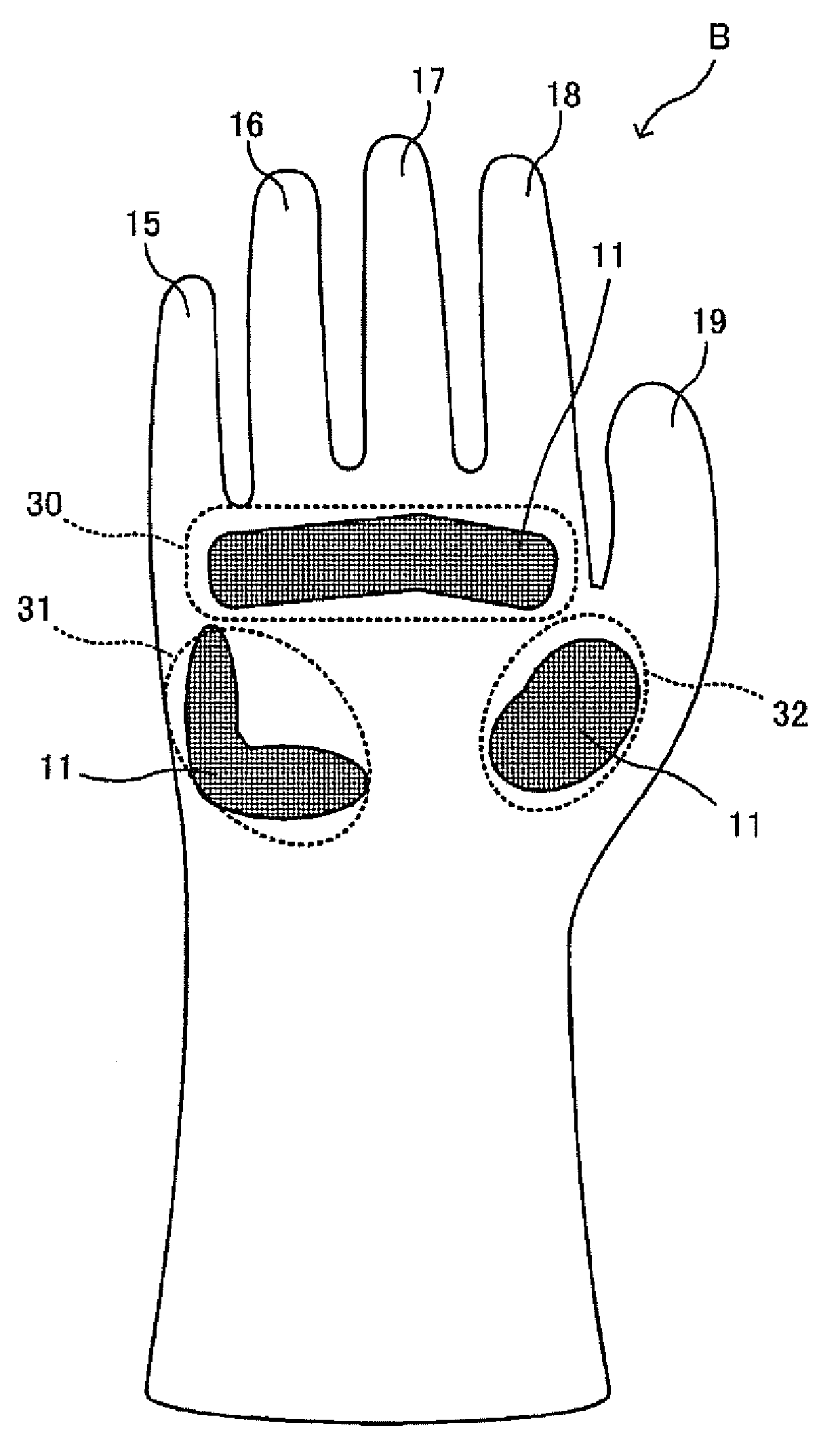
[0096]Next, an example 2 is explained. While the fabric material is affixed to the respective finger portions in the work glove A described in the above-mentioned example 1, a work glove B according to this example 2 is characterized in that a fabric material is affixed to a palm portion of the work glove 13. In the explanation made hereinafter, constitutional parts substantially equal to the constitutional parts of the above-mentioned example are given same symbols and the explanation of these constitutional parts is omitted.

[0097]In the work glove B, to be specific, the meshed fabric 11 is affixed to a four-finger palm position 30, a little finger hill position 31, and a thumb hill position 32.

[0098]According to the work glove B having such a constitution, it is possible to remarkably enhance wear resistance and a slip preventing property of the palm portion of the work glove B. It is needless to say that, in the same manner as the above-mentioned work glove A, al...

example 3

[0099][Example 3]

[0100]Next, a work glove C according to an example 3 is shown in FIG. 6. The work glove C is characterized in that a fabric material is formed into a glove shape, and is mounted on and affixed to a glove body 10.

[0101]According to the work glove C having such a constitution, it is possible to enhance a slip preventing property of the whole hand including respective finger portions and a palm portion of the glove body 10. In such a constitution, in the case where a slip preventing property is unnecessary on a back of the work glove C, a fabric material formed into a glove shape having no back portion may be used. It is needless to say that, in the same manner as the above-mentioned work gloves A and B, also in the work glove C, in place of the knitted fabric 11, a cloth 24 or a meshed fabric 26 may be affixed to the glove body 10, or a mixed body formed of the cloth 24 and the meshed fabric 26 may be affixed to the glove body 10.

[0102]Next, an example of the manufact...


PUM


Abstract

Provided is a work glove which has further improved wear resistance and workability while ensuring functions such as dielectric breakdown strength and water proofing. In such a work glove, a fabric material, which is formed of one selected from cloth, knitted fabric and meshed fabric and has a predetermined area, is affixed to an outer surface of a glove base which is made of an elastic material, and a coating film having a higher friction coefficient than the fabric material is formed on a surface of the fabric material.

Description

CROSS REFERENCE TO RELATED APPLICATIONS[0001]This application claims priority to International Ser. No. PCT / JP2011 / 063010 filed Jun. 7, 2011, the entire contents of which are incorporated herein fully by reference. which in turn claims priority to JP Ser. No. JP 2010-135942, filed on Jun. 15, 2010.TECHNICAL FIELD[0002]The present invention relates to a work glove.BACKGROUND OF THE INVENTION[0003]Conventionally, a number of functions corresponding to characteristics of works are imparted to a work glove.[0004]For example, dielectric breakdown strength is an indispensable physical property for a work glove used in an electric work or the like. Further, the work glove is required to possess other properties such as fingertip workability, slip preventing property, water proofing property and the like.[0005]For forming the work glove possessing such properties, as an example, there has been known a glove where a surface of a base glove formed of a cloth or a knitted fabric is coated with...

Claims


Application Information

Patent Timeline
Patent Type & Authority Patents(United States)
IPC IPC(8): A41D19/015A41D31/00A41D19/00
CPCA41D19/01558A41D31/0072A41D19/015A41D31/265
Inventor TSURU, TAKATOTAKESHITA, TSUYOSHI
Owner TOWA
Learn More