Supercharge Your Innovation With Domain-Expert AI Agents!

Object detection device provided with angle adjustment mechanism

a technology of angle adjustment and object detection, which is applied in the direction of angle measurement, using reradiation, instruments, etc., can solve the problems of increasing the size and cost of the entire device, and the inability to easily attach and remove the automatic angle adjustment unit from the device, so as to reduce the size and cost

Active Publication Date: 2014-10-21
OPTEX CO LTD
View PDF2 Cites 0 Cited by
  • Summary
  • Abstract
  • Description
  • Claims
  • Application Information

AI Technical Summary

Benefits of technology

[0009]In view of the foregoing, the present invention has been deviced to make available an object detection device that is structured to have a reduced size and enable cost reduction and that includes an angle adjustment mechanism which enables an external automatic angle adjustment unit to be attached thereto and detached therefrom with ease, and which enables an automatic angle adjustment to be easily performed from the exterior of the device.
[0013]In these features, both the adjustment-engagement members of the angle adjustment mechanism each have a portion thereof exposed on the front surface of the device, and are disposed adjacent to each other at fixed positions so as not to vertically move relative to each other. Therefore, an external automatic angle adjustment unit can be easily attached to and detached from each adjustment-engagement member. Furthermore, the automatic angle adjustment unit is externally provided, thereby allowing the device to have a reduced size.
[0014]Preferably, the vertical rotation component and the horizontal rotation component are not able to rotate horizontally relative to each other, the horizontal rotation component is supported by a casing of the device so as to be horizontally rotatable, and the horizontal adjustment-engagement member and the vertical adjustment-engagement member are supported by the casing of the device so as to be horizontally rotatable. Therefore, an external automatic angle adjustment unit can easily engage with from the exterior and drive both of the adjustment-engagement members with a simplified structure, and attachment and detachment thereof are also performed with an enhanced ease.
[0015]Preferably, an engagement portion of each of the horizontal adjustment-engagement member and the vertical adjustment-engagement member has knurled surfaces in the form of external gear. Therefore, engagement between the external automatic angle adjustment unit and each of the adjustment-engagement members can be assuredly performed.
[0016]Preferably, the vertical rotation component is provided with a shaft portion having an external screw portion. The horizontal rotation component is screwed with the external screw portion. The vertical rotation component is supported so as to be rotatable about the horizontal axis relative to the horizontal rotation component, and so as not to be rotatable about the vertical axis relative to the horizontal rotation component. The vertical rotation component rotates about the horizontal axis when the shaft portion of the vertical rotation component is moved in an axial direction thereof due to rotation of the vertical adjustment-engagement member. Therefore, the vertical rotation component can be tilted upward and downward due to rotation of the vertical adjustment-engagement member, with a simplified structure.
[0018]In these features, the object detection system is formed, at reduced cost, so as to have a reduced size, the object detection device and the external automatic angle adjustment unit are easily attached to and detached from each other, and an automatic angle adjustment can be easily performed for the object detection device from the exterior thereof.

Problems solved by technology

However, in Japanese Laid-Open Patent Publication No. 2009-87240, in order to automatically adjust the optical axis, an automatic angle adjustment section including: a driving motor for adjusting a vertical angle and a horizontal angle; and a control section thereof, is incorporated in the device, thereby increasing the size and cost of the entirety of the device.
Therefore, there is a structural problem that the automatic angle adjustment unit cannot be easily attached to and detached from the device.

Method used


Image

  • Object detection device provided with angle adjustment mechanism
  • Object detection device provided with angle adjustment mechanism
  • Object detection device provided with angle adjustment mechanism

Examples


first embodiment

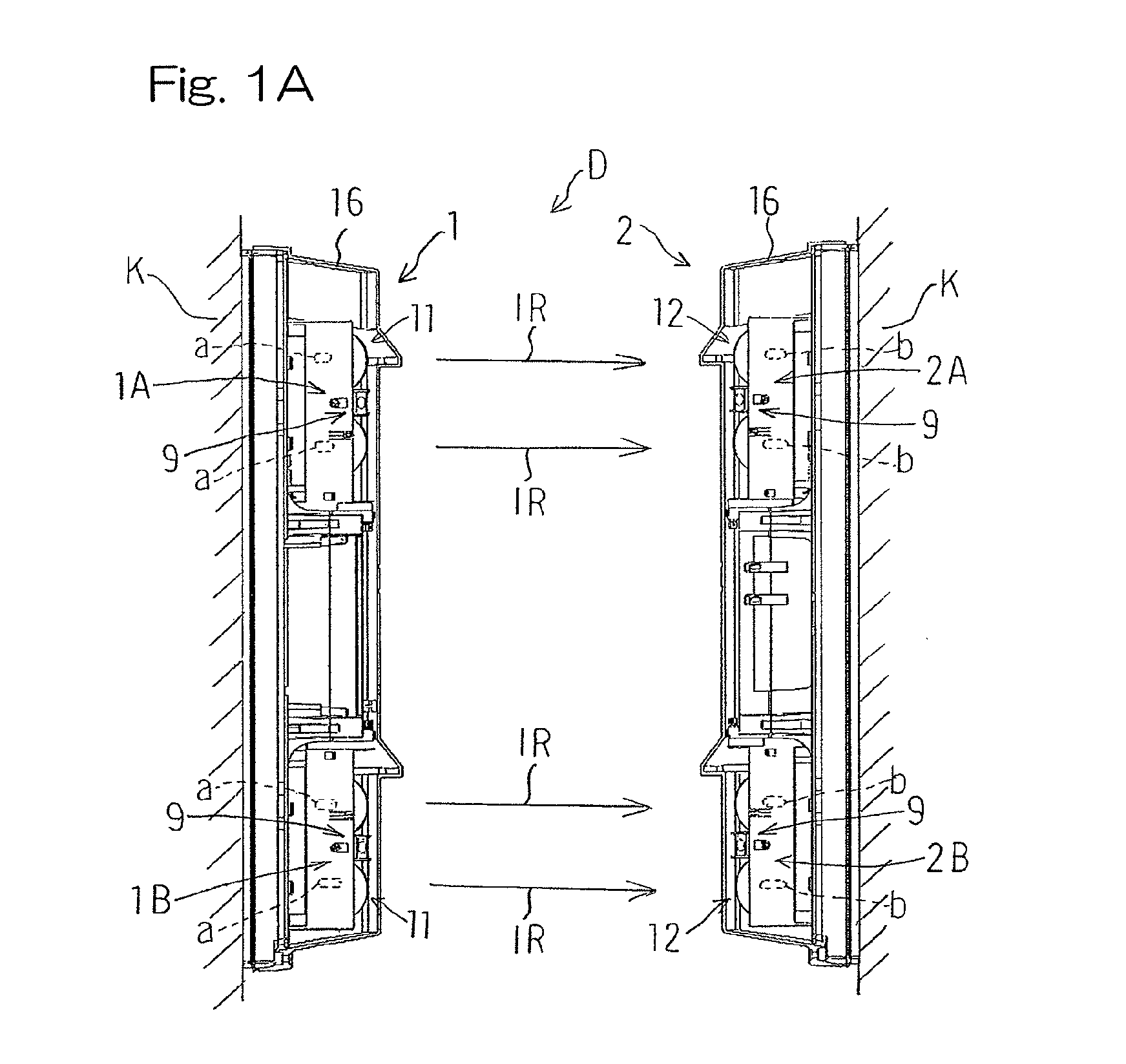
[0036]Hereinafter, preferred embodiments of the present invention will be described with reference to the drawings. FIG. 1A is a schematic side view of an object detection device having an angle adjustment mechanism according to the present invention. An object detection device D includes: a transmission section 1 having a transmitter 1A and a transmitter 1B; and a reception section 2 having a receiver 2A and a receiver 2B. Each of the transmitter 1A and the transmitter 1B includes transmitting elements a. The transmitters 1A and 1B are disposed one above the other. In the present embodiment, the transmitter 1A is disposed above the transmitter 1B. The receiver 2A and the receiver 2B are disposed so as to oppose the transmitter 1A and the transmitter 1 B, and each include receiving elements b for receiving detection beams such as infrared rays (IR) transmitted from the transmitters 1A and 1B. The receivers 2A and 2B are disposed one above the other. In the present embodiment, the re...

second embodiment

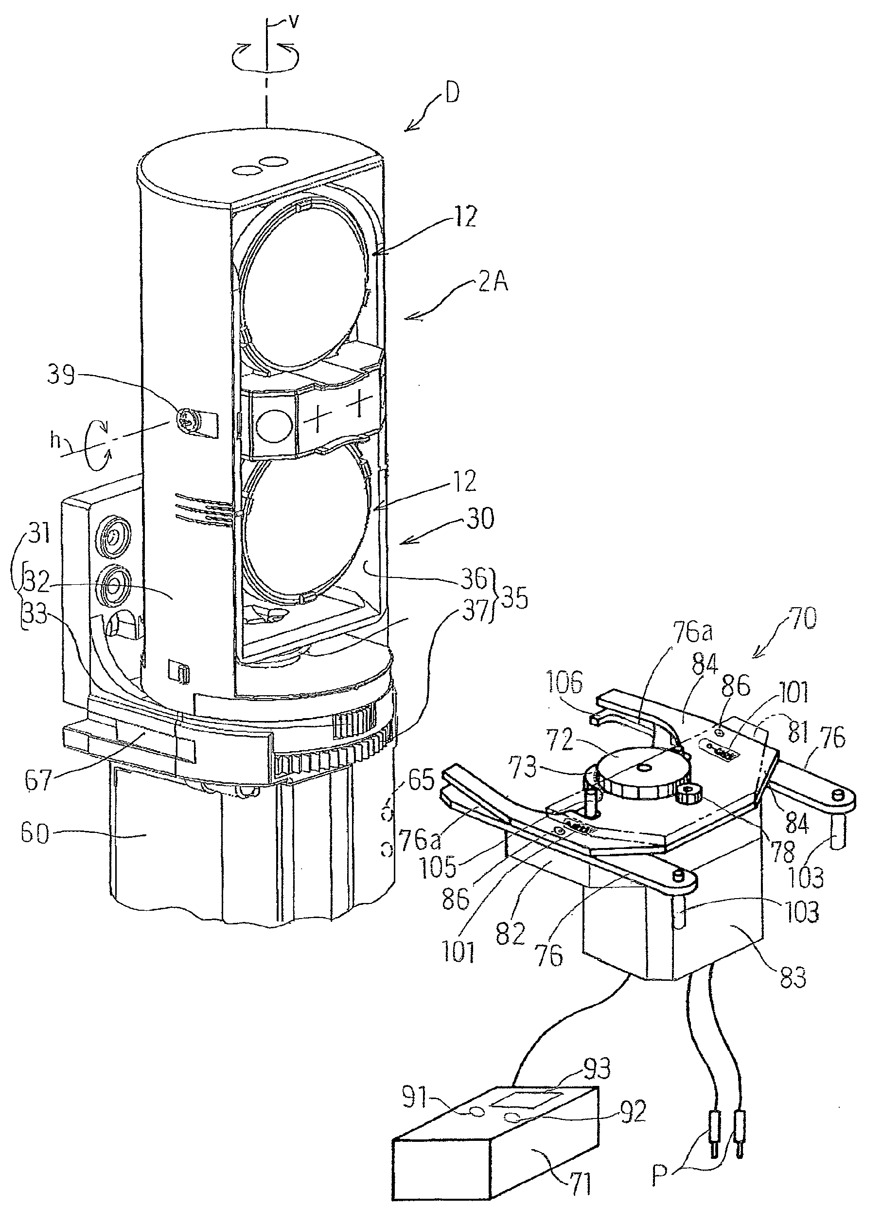
[0060]FIG. 6 is a perspective view of an object detection system according to the present invention. The object detection system includes: the automatic angle adjustment unit 70 that is engaged with the angle adjustment mechanism 30 of the receiver 2A of the object detection device D, and that adjusts an angle of the optical system 12 to the horizontal axis and an angle of the optical system 12 to the vertical axis, to automatically adjust the optical axis from the exterior of the device; and a control box 71 for controlling the automatic angle adjustment unit 70, in addition to the object detection device D. The control box 71 includes a probe P for input of a detection signal level. The automatic angle adjustment unit 70 includes: engagement-drive transmission sections 72 and 73 acting as horizontal and vertical adjustment gears that removably engage with the horizontal and the vertical adjustment dials 33 and 37 of the angle adjustment mechanism 30 of the receiver 2A, from the fr...


PUM


Abstract

A horizontal adjustment-engagement member (33) of an object detection device (D) drives the horizontal rotation component (32) to adjust a horizontal angle of a detection unit (11, 12), and a vertical adjustment-engagement member (37) drives the vertical rotation component (36) to adjust a vertical angle of a detection unit. Both adjustment-engagement members (33 and 37) are positioned adjacent to each other at fixed positions such that portions thereof are exposed on a front surface of the device (D), are removably engaged with an external automatic angle adjustment unit (70) from front surfaces, and are automatically adjusted by a driving force of the automatic angle adjustment unit (70) based on a signal level of a detection signal outputted by level output section (7).

Description

CROSS REFERENCE TO THE RELATED APPLICATION[0001]This application is based on and claims Convention priority to Japanese patent application No. 2011-246778, filed Nov. 10, 2011, the entire disclosure of which is herein incorporated by reference as a part of this application.BACKGROUND OF THE INVENTION[0002]1. Field of the Invention[0003]The present invention relates to an object detection device that includes: a transmitter having a transmitting detection unit for transmitting detection beams for object detection; a receiver having a receiving detection unit for receiving the detection beams and outputting a detection signal; and an angle adjustment mechanism for adjusting angles of the detection units.[0004]2. Description of Related Art[0005]In general, a transmitter-receiver opposing type object detection device includes: a transmitter having a transmitting optical system (detection unit) for transmitting detection beams, such as infrared rays, for object detection; and a receiver ...

Claims


Application Information

Patent Timeline
Patent Type & Authority Patents(United States)
IPC IPC(8): G01V8/20G01B11/26
CPCG01V8/20G01S17/88G08B13/183
Inventor IKEDA, HIROYUKI
Owner OPTEX CO LTD
Features
  • R&D
  • Intellectual Property
  • Life Sciences
  • Materials
  • Tech Scout
  • Unparalleled Data Quality
  • Higher Quality Content
  • 60% Fewer Hallucinations
Learn More