
Parking position adjustment device

a technology of positioning position and adjustment device, which is applied in the direction of navigation instruments, instruments, transportation and packaging, etc., can solve the problems of inability to park, driver rush, and inability to correctly park in the center of the parking space, and achieve the effect of easy setting of the movement path

Active Publication Date: 2014-10-21
AISIN SEIKI KK
View PDF13 Cites 42 Cited by
  • Summary
  • Abstract
  • Description
  • Claims
  • Application Information

AI Technical Summary

Benefits of technology

The patent describes a parking space adjustment device that allows drivers to easily move their vehicles to desired positions within a parking space. The device specifies the current position of the vehicle and calculates a movement path to the target parking position within the specified space. This reduces the processing load and allows for a low-cost device to be developed. The driver only needs to follow the movement path and can quickly and correctly position the vehicle, improving parking efficiency and reducing the burden on the driver's time. Additionally, the device allows for temporary parking in a space and quickly re-parking in a desired position, making the driving experience more convenient for the driver and reducing the impact on neighboring vehicles.

Problems solved by technology

When parking a vehicle in a parking space, there are cases where it is not possible to park in the center of the parking space on a single try without changing directions depending on the spacing of the parking spaces, the width of the road connected to the parking spaces, and so on.
There are also situations where, for example, a following vehicle is present, which can cause a driver to rush and thus be unable to correctly park in the center of the parking space.

Method used


Image

  • Parking position adjustment device
  • Parking position adjustment device
  • Parking position adjustment device

Examples


first embodiment

[0044]1. First Embodiment

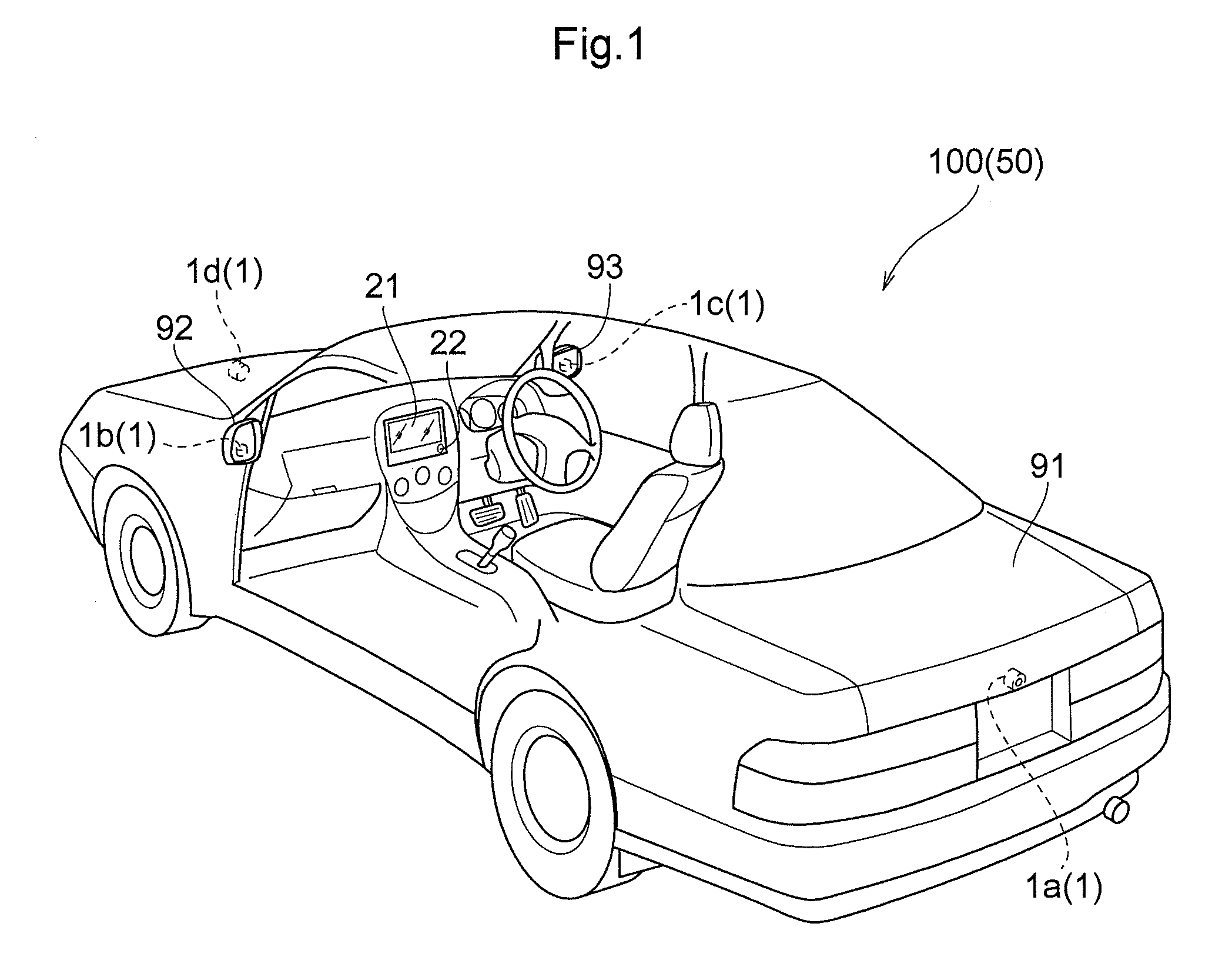
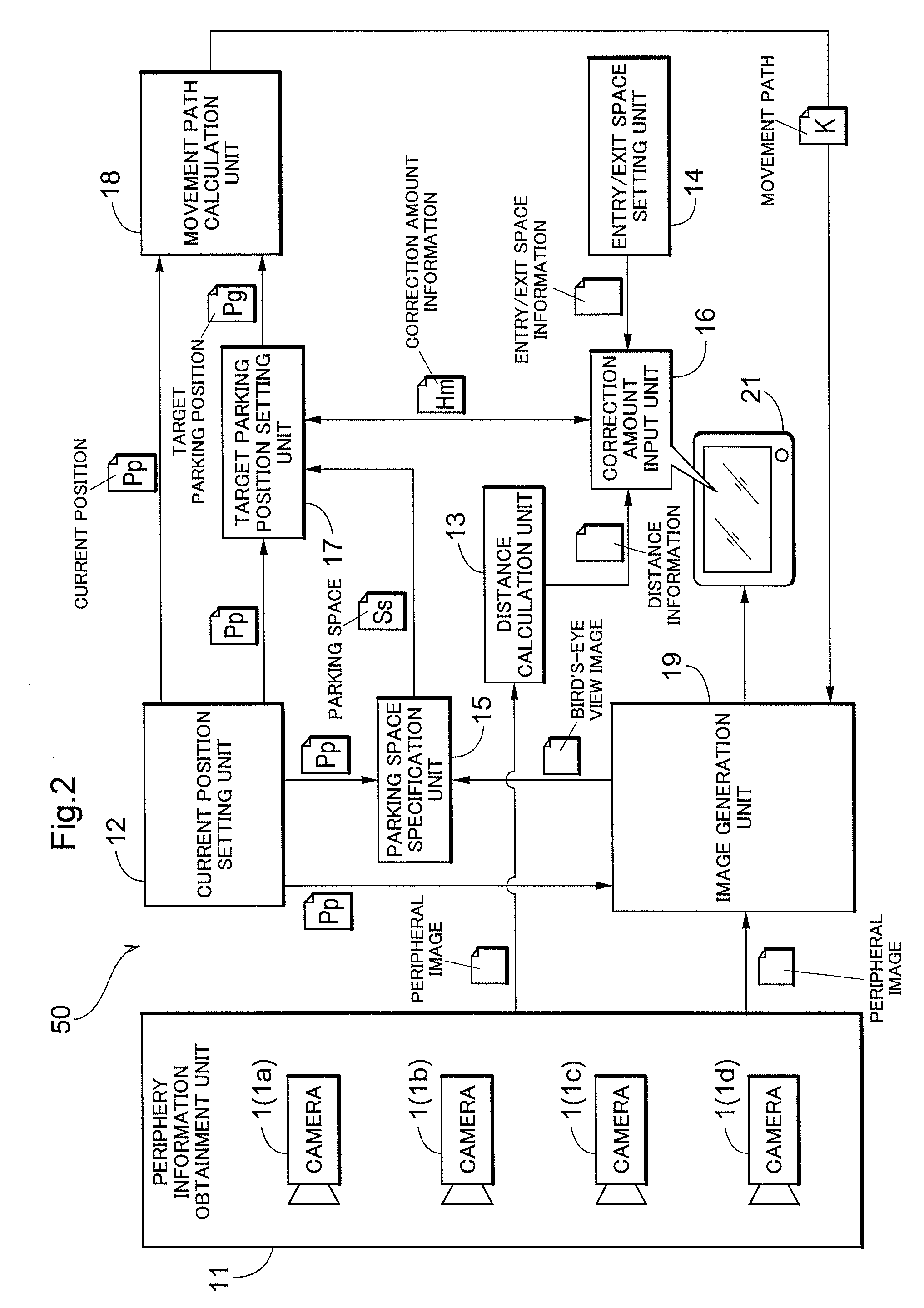
[0045]Hereinafter, embodiments of the present invention will be described in detail. FIG. 1 is a perspective view illustrating an overview of a vehicle 100 provided with a parking position adjustment device 50 according to the present invention. A rear camera 1a is provided on a rear area of the vehicle 100 (in the present example, on a trunk door 91). A left side camera 1b is provided on a lower area of a left side mirror 92 on a left-front door, whereas a right side camera 1c is provided on a lower area of a right side mirror 93 on a right-front door. Furthermore, a forward camera 1d is provided on a front area of the vehicle. In the following descriptions, the cameras 1a through 1d will be collectively referred to as “cameras 1” (vehicle-mounted cameras) where appropriate.

[0046]The cameras 1 are digital cameras that employ image sensors such as CCDs (charge coupled devices) or CISs (CMOS image sensors), capture two-dimensional images in time series at 15-...

second embodiment

[0072]2. Second Embodiment

[0073]Next, a second embodiment will be described. The aforementioned first embodiment describes an occupant inputting the correction amount for the vehicle 100 him / herself. The parking position adjustment device 50 according to the present embodiment, however, differs from the parking position adjustment device 50 according to the aforementioned first embodiment in that the correction amount is automatically inputted. The rest of the configuration is the same as in the first embodiment, and thus the following descriptions will focus on this difference.

[0074]FIG. 5 is a block diagram schematically illustrating the configuration of the parking position adjustment device 50 according to the second embodiment. The parking position adjustment device 50 according to the present embodiment includes a correction amount calculation unit 30 in addition to the configuration described in the first embodiment and illustrated in FIG. 1. In addition, the present embodime...


PUM


Abstract

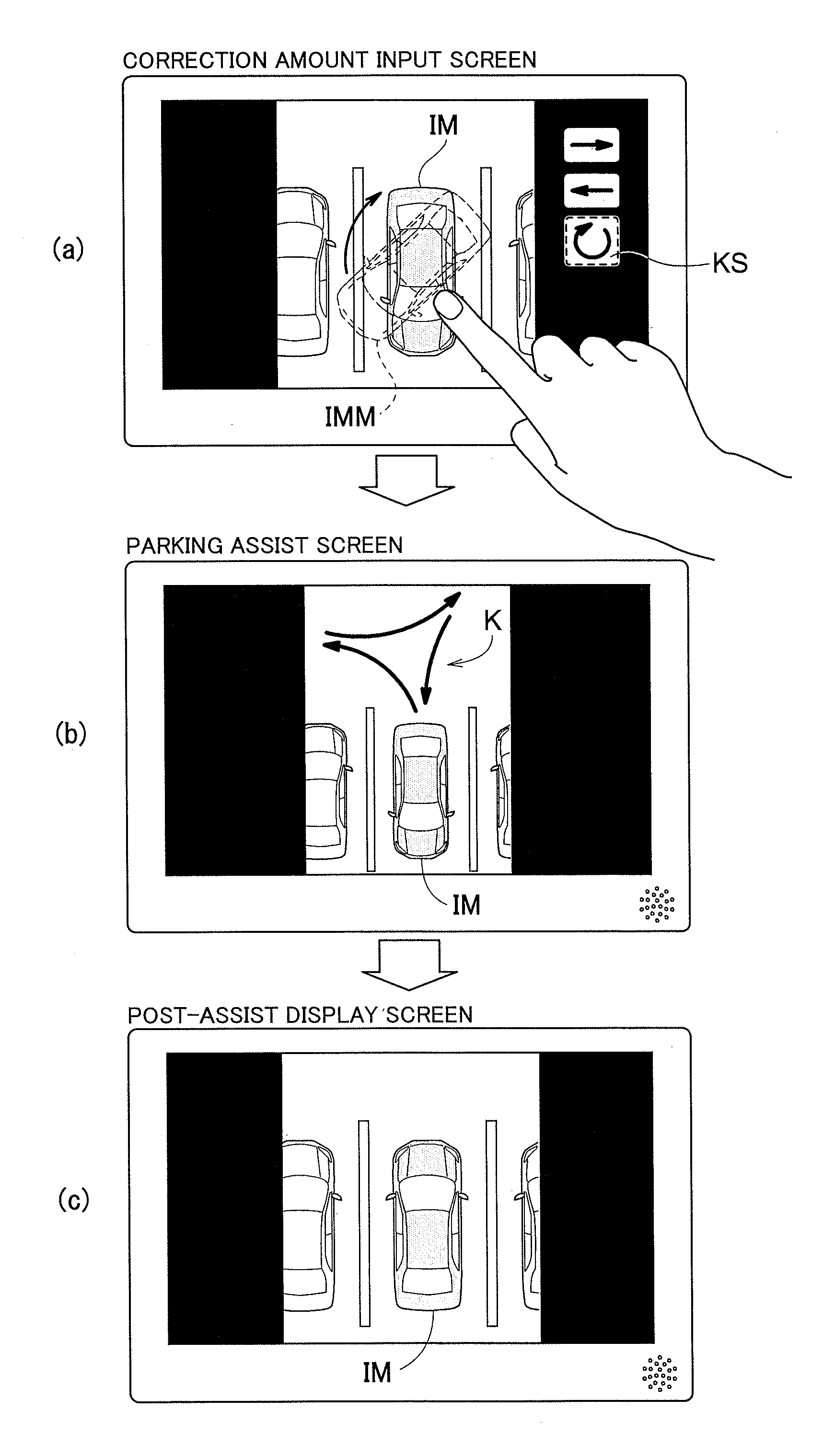
A parking position adjustment device that assists in correctly changing a parking position within a parking space in which a vehicle has already parked is provided.The parking position adjustment device includes: a current position setting unit that sets the position in which a vehicle is already parked as a current position; a parking space specification unit that specifies a parking space, in which the vehicle is parked, that includes the current position; a target parking position setting unit that sets, within the parking space, a target parking position to which the vehicle is to be moved from the current position; and a movement path calculation unit that calculates a movement path of the vehicle from the current position to the target parking position.

Description

CROSS REFERENCE TO RELATED APPLICATIONS[0001]This application is a National Stage of International Application No. PCT / JP2011 / 072946, filed on Oct. 5, 2011, which claims priority from Japanese Patent Application No. 2010-266751, filed Nov. 30, 2010, the contents of all of which are incorporated herein by reference in their entirety.TECHNICAL FIELD[0002]The present invention relates to parking position adjustment devices that adjust the position of a vehicle that has already been parked in a parking space.BACKGROUND ART[0003]When parking a vehicle in a parking space, there are cases where it is not possible to park in the center of the parking space on a single try without changing directions depending on the spacing of the parking spaces, the width of the road connected to the parking spaces, and so on. There are also situations where, for example, a following vehicle is present, which can cause a driver to rush and thus be unable to correctly park in the center of the parking space...

Claims


Application Information

Patent Timeline
Patent Type & Authority Patents(United States)
IPC IPC(8): B60R1/00G06F19/00G06F7/00G01C21/00B62D15/02G01M17/00
CPCB60R2300/806B62D15/0285B60R1/00G01C21/00B62D15/027B62D15/028B60R1/27
Inventor IKEDA, KEIGOTANAKA, YUKADOWAKI, JUN
Owner AISIN SEIKI KK
Learn More