Load sensing system, working machine comprising the system, and method for controlling a hydraulic function

a technology of load sensing and working machine, which is applied in the direction of mechanical equipment, couplings, constructions, etc., can solve the problems of unstable steering of orbitrol, easy limitation of electrically controlled functions, and inability to control the steering of orbitrol, so as to reduce stable steering of orbitrol, and the effect of reducing the maximum possible hydraulic power outpu

Active Publication Date: 2014-10-28
VOLVO CONSTR EQUIP AB
View PDF11 Cites 12 Cited by
  • Summary
  • Abstract
  • Description
  • Claims
  • Application Information

AI Technical Summary

Benefits of technology

[0012]By means of achieving a variable control pressure in this way, the pump can for example be at a low basic level and set on a pressure which is only 5-10 bar higher, that is to say as small a pressure increase as possible (the limit is defined by requirements on lubricating and cooling ability). If a higher control pressure is required, for example 30 bar, the electrically controlled pump control valve (LS valve) has to compensate for this. According to an example, the actuator (cylinder) has the pressure level 100 bar. The LS valve then sets the pressure level 125 bar and the pump itself adds an additional 5 bar, which means that the pump pressure becomes 130 bar in total. Thereby, lower drag losses (idling losses) can be obtained, thanks to low standby pressure. When no flow is required from the pump, its idles at for example 5 bar instead of 30 bar.
[0025]According to another preferred example, the method comprises the steps of detecting the position of an operator-controlled element associated with said hydraulic function, and actuating a control valve arranged between the pump and the actuator based upon the detected position of the operator-controlled element. The method preferably comprises the step of coordinating the control of the pump and the actuation of the control valve. This creates prerequisites for lower control losses at smaller output flows to the functions. The lower the flow requested for a function is, the lower a control pressure can be used, since the slide in the control valve is opened more.

Problems solved by technology

According to prior art, there are problems to get the orbitrol steering stable, since resonances with respect to pressure fluctuations arise.
The electrically controlled functions can easily be limited, but the problem is the steering orbitrol (which is not electrically controlled).

Method used


Image

  • Load sensing system, working machine comprising the system, and method for controlling a hydraulic function
  • Load sensing system, working machine comprising the system, and method for controlling a hydraulic function
  • Load sensing system, working machine comprising the system, and method for controlling a hydraulic function

Examples


Embodiment Construction

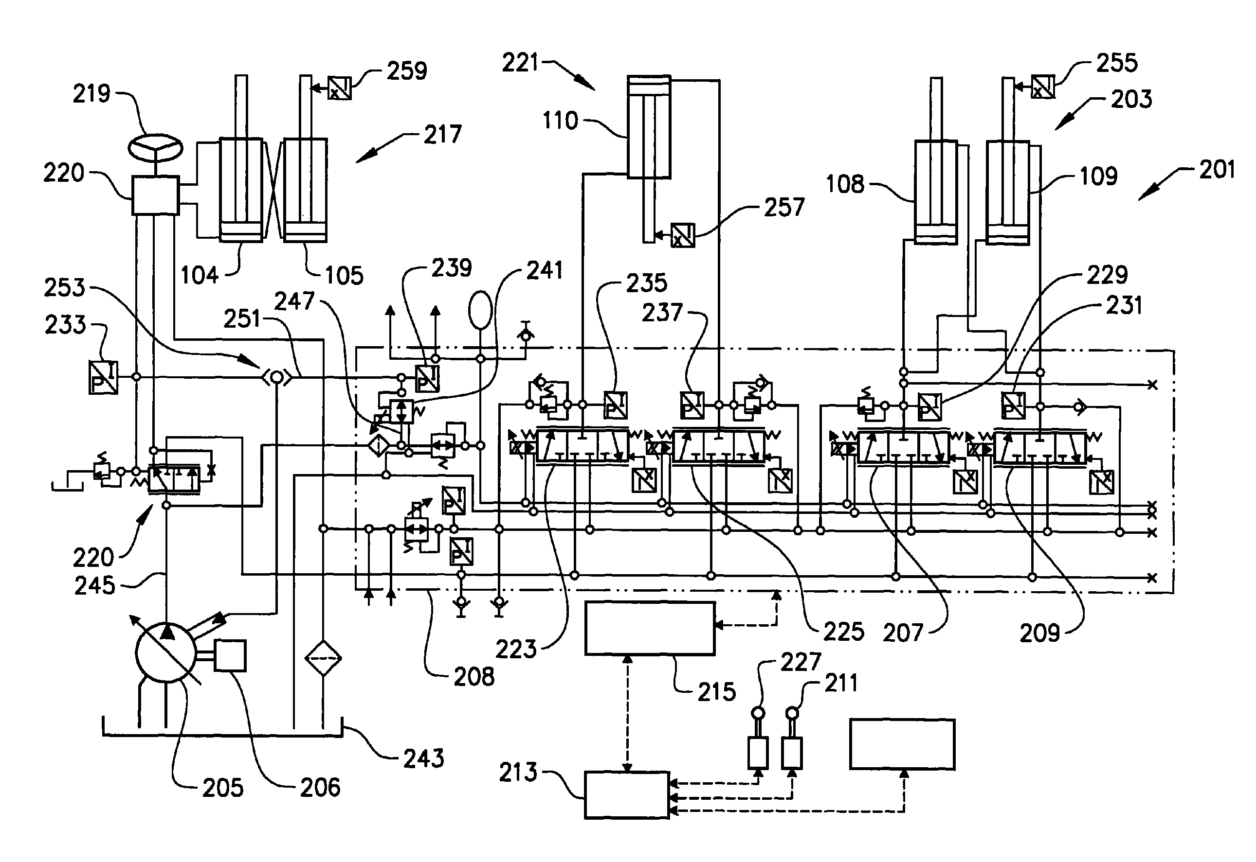
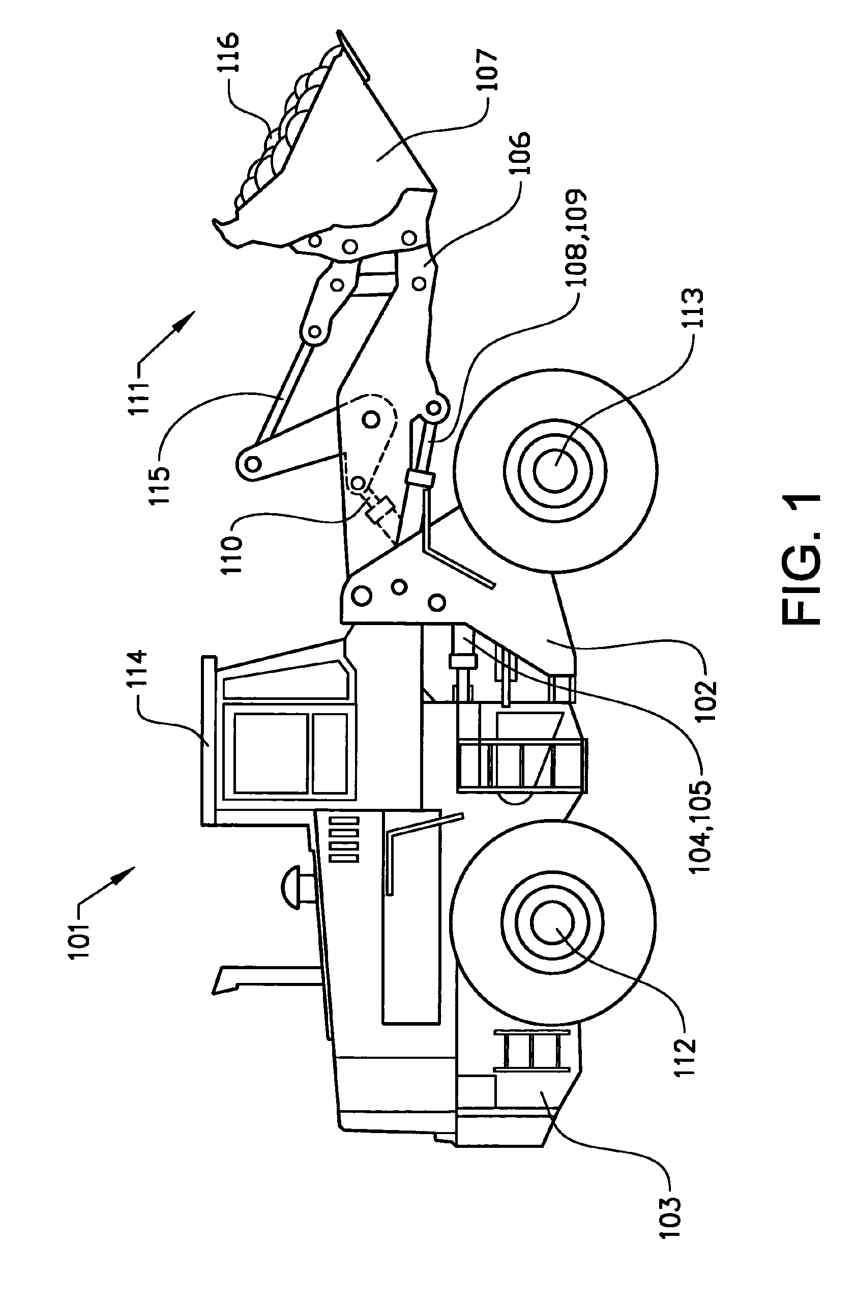
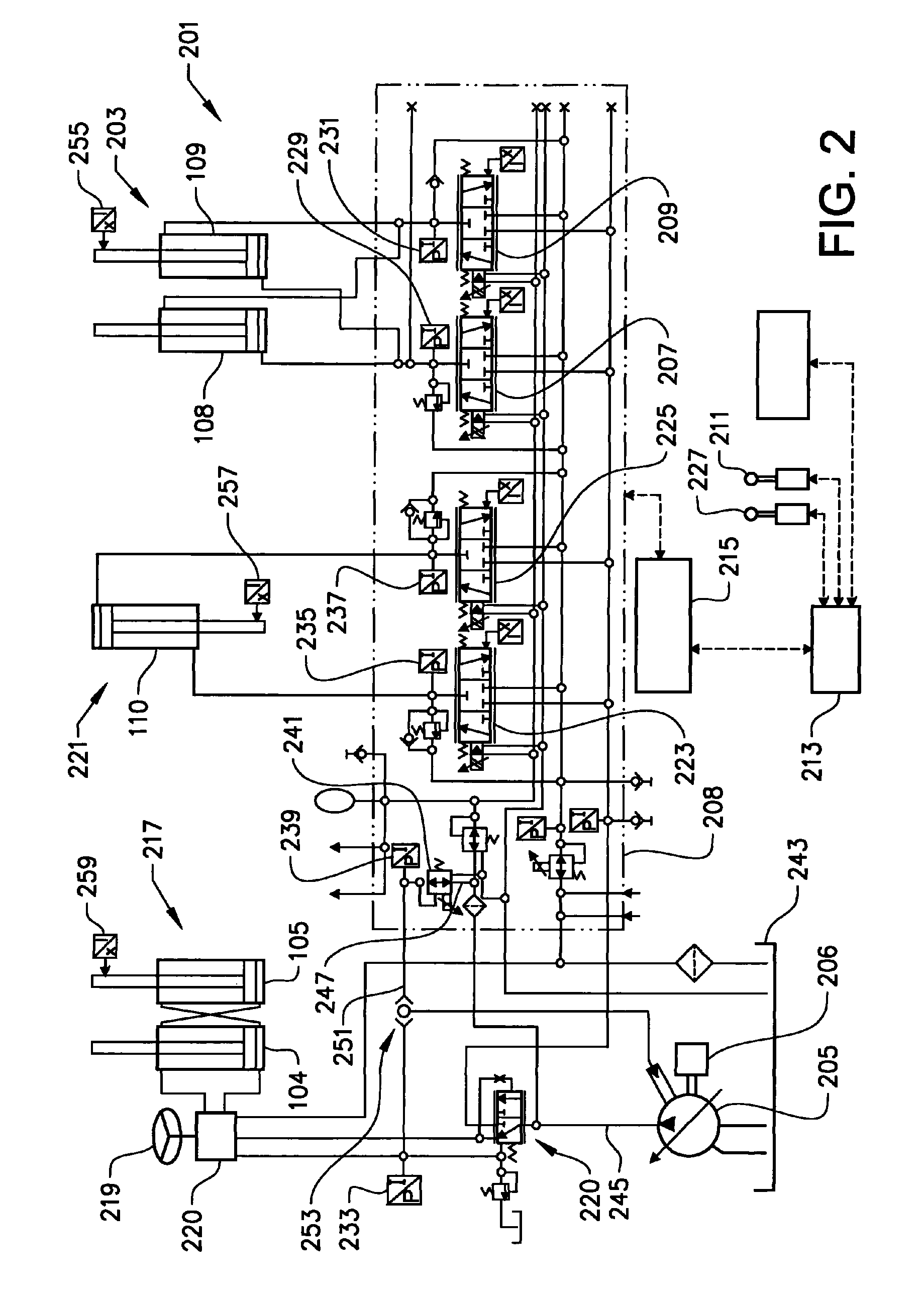
[0030]FIG. 1 shows a side view of a wheel loader 101. The wheel loader 101 comprises a front vehicle section 102 and a rear vehicle section 103, said sections each comprising a frame and a pair of drive shafts 112, 113. The rear vehicle section 103 comprises a operator's cab 114. The vehicle sections 102, 103 are connected to each other in such a way that they can be pivoted relative to each other about a vertical axis by means of two hydraulic cylinders 104, 105 which are connected to the two sections. Accordingly, the hydraulic cylinders 104, 105 are disposed on different sides of a centre line in the longitudinal direction of the vehicle for steering, or turning the wheel loader 101.

[0031]The wheel loader 101 comprises an equipment 111 for handling objects or material. The equipment 111 comprises a load-arm unit 106 and an implement 107 in the form of a bucket which is fitted on the load-arm unit. Here, the bucket 107 is filled with material 116. A first end of the load-arm unit ...


PUM


Abstract

A load sensing system includes a first assembly of actuators for controlling a first hydraulic function, a pump adapted to supply the actuators with pressurized hydraulic fluid, an electrically controlled valve adapted to control the output pressure of the pump via a hydraulic signal, a first pressure sensor for detecting a load pressure of the first actuator assembly, and a control unit adapted to receive a signal with information about the load pressure detected by the first pressure sensor and to generate a control signal, corresponding to the detected load pressure, to the electrically controlled valve.

Description

BACKGROUND AND SUMMARY[0001]The present invention relates to a load sensing system, comprising a first assembly of actuators for controlling a first hydraulic function, a pump adapted to supply said actuators with pressurized hydraulic fluid, and an electrically controlled valve adapted to control the output pressure of the pump via a hydraulic signal. In particular, the invention relates to a working machine comprising the system. A working machine in the form of a wheel loader has several different work functions which are hydraulically controlled, such as lifting and tilting of an implement and steering of the machine. As a rule, the actuators are constituted of linear motors in the form of hydraulic cylinders. The invention further relates to a method for controlling a hydraulic function.[0002]Below, the invention will be described in connection with the operation of a wheel loader. This is a preferred, but by no means limiting application of the invention. The invention can for...

Claims


Application Information

Patent Timeline
Patent Type & Authority Patents(United States)
IPC IPC(8): F15B11/16E02F9/22
CPCF15B2211/6313F15B2211/20523F15B11/165F15B2211/6336E02F9/2228E02F9/2235F15B2211/20546F15B2211/6346F15B11/162F15B2211/6309F15B2211/253F15B2211/6316F15B2211/61E02F9/2296F15B2211/3144F15B2211/30565
Inventor VIGHOLM, BOEKVALL, ANDREAS
Owner VOLVO CONSTR EQUIP AB
Why Eureka
Try Eureka