Method for manufacturing alignment layer

a manufacturing method and alignment layer technology, applied in non-linear optics, instruments, optics, etc., can solve the problems of inability to achieve wide view, and easy generation of dust or static electricity, etc., to achieve the effect of wide view and preferable process yield ra

Inactive Publication Date: 2014-10-28
CHUNGHWA PICTURE TUBES LTD
View PDF4 Cites 2 Cited by
  • Summary
  • Abstract
  • Description
  • Claims
  • Application Information

AI Technical Summary

Benefits of technology

[0007]Accordingly, the invention is directed to a method for manufacturing an alignment layer, which may reduce the occurrence of uneven alignment and dark state light leakage, thereby having a more preferable process yield rate and achieving the effect of wide view.
[0017]Based on the above, in the invention, the method for manufacturing the alignment layer is adopted to the alignment material having the ultraviolet reactive functional group. The ultraviolet light passes through the ultraviolet polarizer firstly and irradiates to the pre-baked alignment material, and then the post-baking process is performed to cure the alignment material. Therefore, the alignment layer manufactured in the invention can have a more preferable aligning effect. Furthermore, as compared with the conventional aligning method (that is adopted to the contact type), the method for manufacturing the alignment layer in the invention may effectively reduce the probability of the alignment layer being damaged and prevent the poor alignment and dark state light leakage caused by the generated static electricity or the powders and particles. Accordingly, the method for manufacturing the alignment layer in the invention may have a more preferable process yield rate.

Problems solved by technology

However, such method is required a roller to perform an alignment rubbing process on a surface of a glass substrate.
In this way, a multi-domain alignment can not be performed for each of the pixels, and thus the effect of wide view can not be achieved.
Furthermore, dust or static electricity may be easily generated on the alignment layer by the manufacturing method, in the contact manner.
Additionally, since the roller is required for performing the alignment on the glass substrate, such method can not be easily applied to the large-sized panel fabrication under the circumstances that the size of the glass substrate gradually increases, so that uneven alignment can be easily occurred.

Method used


Image

  • Method for manufacturing alignment layer
  • Method for manufacturing alignment layer
  • Method for manufacturing alignment layer

Examples


Embodiment Construction

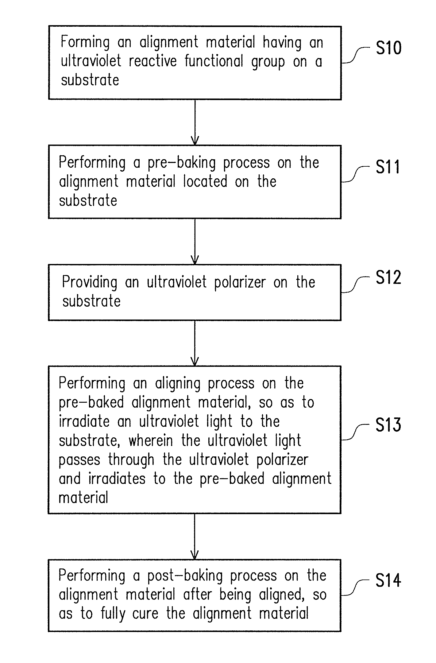
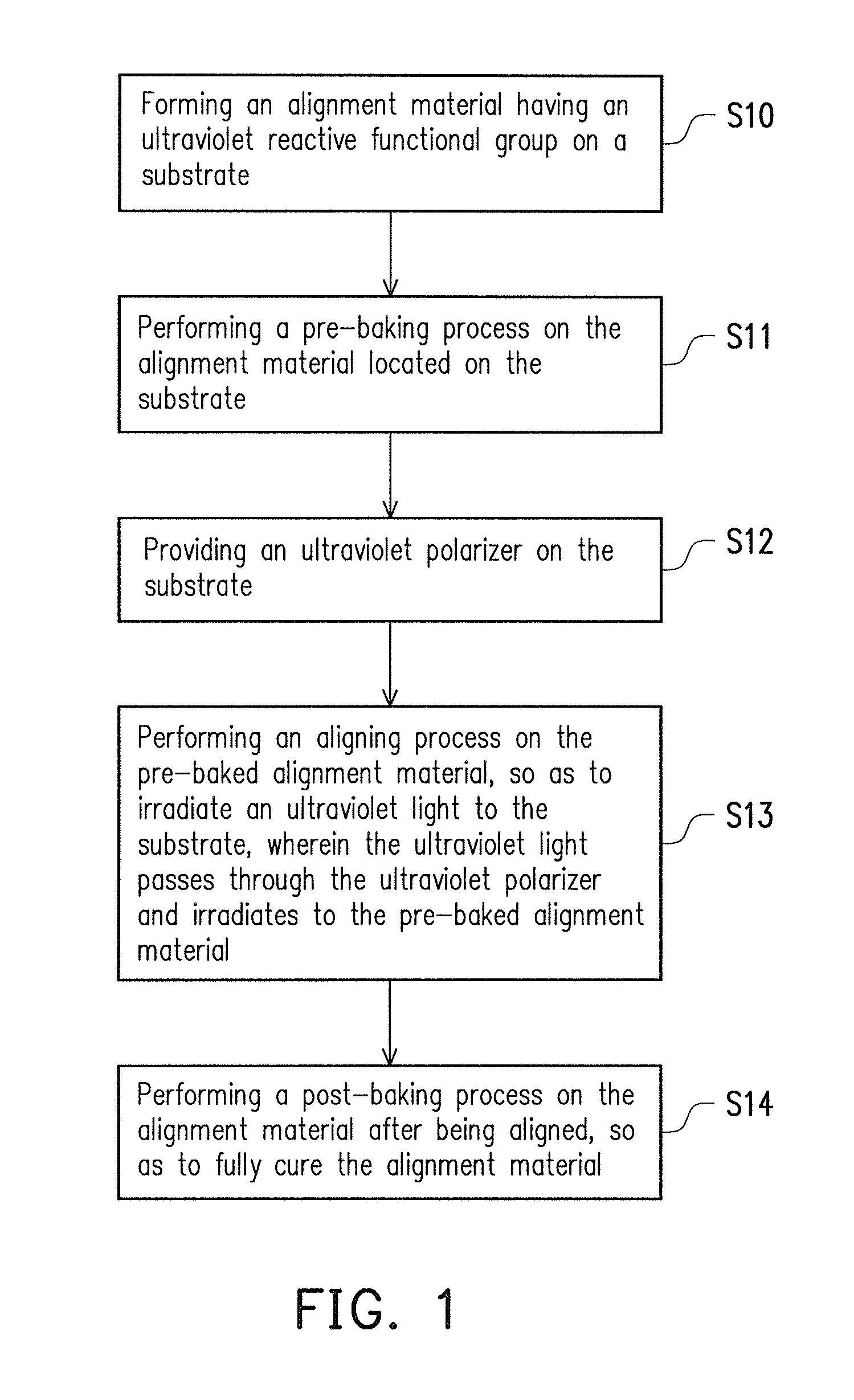
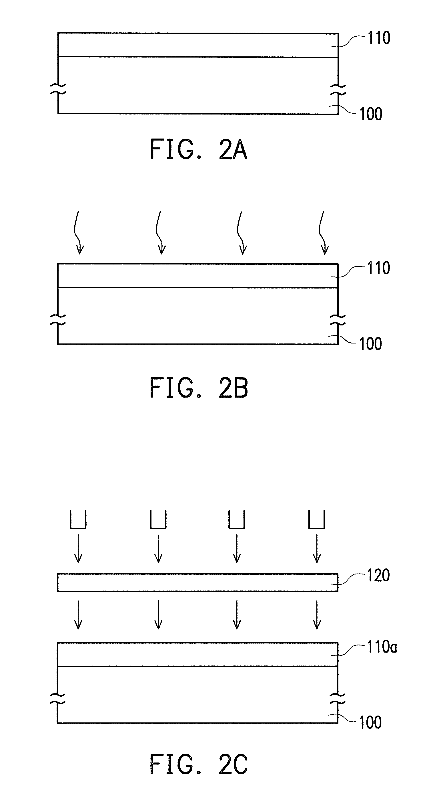
[0022]FIG. 1 schematically illustrates a flowchart diagram of a method for manufacturing an alignment layer according to an embodiment of the invention. FIG. 2A through FIG. 2E are schematic cross-sectional views of the method for manufacturing the alignment layer depicted in FIG. 1. Firstly, referring to FIG. 1 and FIG. 2A together, in the embodiment, an alignment material 110 having an ultraviolet reactive functional group is formed on a substrate 100. In the embodiment, the material of the alignment material 110 can be a polymeric material having a photo reactive functional group, such as polyimide or polyamide acid. The substrate 100 can be a colour filter substrate or an active device array substrate.

[0023]It is noted that, before the alignment material 110 is formed on the substrate 100, a cleaning process can be performed firstly on the substrate 100, which may also effectively enhance the product reliability of the alignment layer formed subsequently, besides the bondability...


PUM

PropertyMeasurementUnit
temperatureaaaaaaaaaa
energyaaaaaaaaaa

Abstract

A method for manufacturing an alignment layer is provided. An alignment material having an ultraviolet reactive functional group is formed on a substrate. A pre-baking process is performed on the alignment material located on the substrate. An ultraviolet polarizer is provided on the substrate. An aligning process is performed on the pre-baked alignment material, so as to irradiate an ultraviolet light to the substrate. The ultraviolet light passes through the ultraviolet polarizer and irradiates to the pre-baked alignment material. A post-baking process is performed on the alignment material after being aligned, so as to fully cure the alignment material.

Description

CROSS-REFERENCE TO RELATED APPLICATION[0001]This application claims the priority benefit of Taiwan application serial no. 101144539, filed on Nov. 28, 2012. The entirety of the above-mentioned patent application is hereby incorporated by reference herein and made a part of this specification.BACKGROUND OF THE INVENTION[0002]1. Field of the Invention[0003]The invention relates to a method for manufacturing an alignment layer, and more particularly, to a method for manufacturing a photo alignment layer.[0004]2. Description of Related Art[0005]One common liquid crystal panel is mainly composed of two substrates and a liquid crystal layer disposed between the two substrates. Regardless of whether an active matrix liquid crystal display or a passive matrix liquid crystal display is applied, an alignment layer is required to be provided on the two substrates. The alignment layer is applied to align liquid crystal molecules, in order for the liquid crystal molecules to represent as being t...

Claims


Application Information

Patent Timeline
Patent Type & Authority Patents(United States)
IPC IPC(8): G02F1/1337
CPCG02F1/133788
Inventor HSIEH, CHIA-SHENGFU, HSIN-MINWU, HUNG-YULIAN, JAN-TIAN
Owner CHUNGHWA PICTURE TUBES LTD
Why Eureka
Try Eureka