
Electrical junction box

a junction box and junction box technology, applied in the direction of coupling device details, coupling device connection, printed circuits, etc., can solve the problems of the vehicle attachment direction, reducing the degree of freedom with respect to the shape of the vehicle fixing portion, and reducing the risk of flexural deformation of the upper case. , to achieve the effect of restoring the force from flexural deformation, reducing the risk

Inactive Publication Date: 2014-11-04
SUMITOMO WIRING SYST LTD
View PDF9 Cites 11 Cited by
  • Summary
  • Abstract
  • Description
  • Claims
  • Application Information

AI Technical Summary

Benefits of technology

The technical effects of this patent are good stability and reliability of connection with the connector, efficient space utilization, and improved flexibility in attachment to a vehicle. The connector lock on the second case prevents the first case from being lifted up by forces on the connector and displacement of the connector relative to a circuit board. The vehicle fixing portion on the second case facilitates securing space in the periphery of the connector and also facilitates inserting and removing the connector. These technical effects make the electrical junction box more reliable, efficient, and flexible in use.

Problems solved by technology

Accordingly, there is the risk of flexural deformation of the upper case if the vehicle fixing portion is subjected to a load due to vibration or the like while the vehicle is traveling or when the electrical junction box is fixed to the vehicle while the connectors are connected.
This flexural deformation could influence the connector locks so that the connector locks are released unexpectedly.
As a result, the vehicle fixing portion can only be formed on a side face of the upper case, thereby restricting the degree of freedom with respect to the shape of the vehicle fixing portion and the vehicle attachment direction.
As a result, the connectors housed in the receptacle displace in the direction of separation from the lower case, and there is the risk of reduced contact points with the connection terminals of the circuit board.
This therefore is not a desirable solution.

Method used


Image

  • Electrical junction box
  • Electrical junction box
  • Electrical junction box

Examples


Embodiment Construction

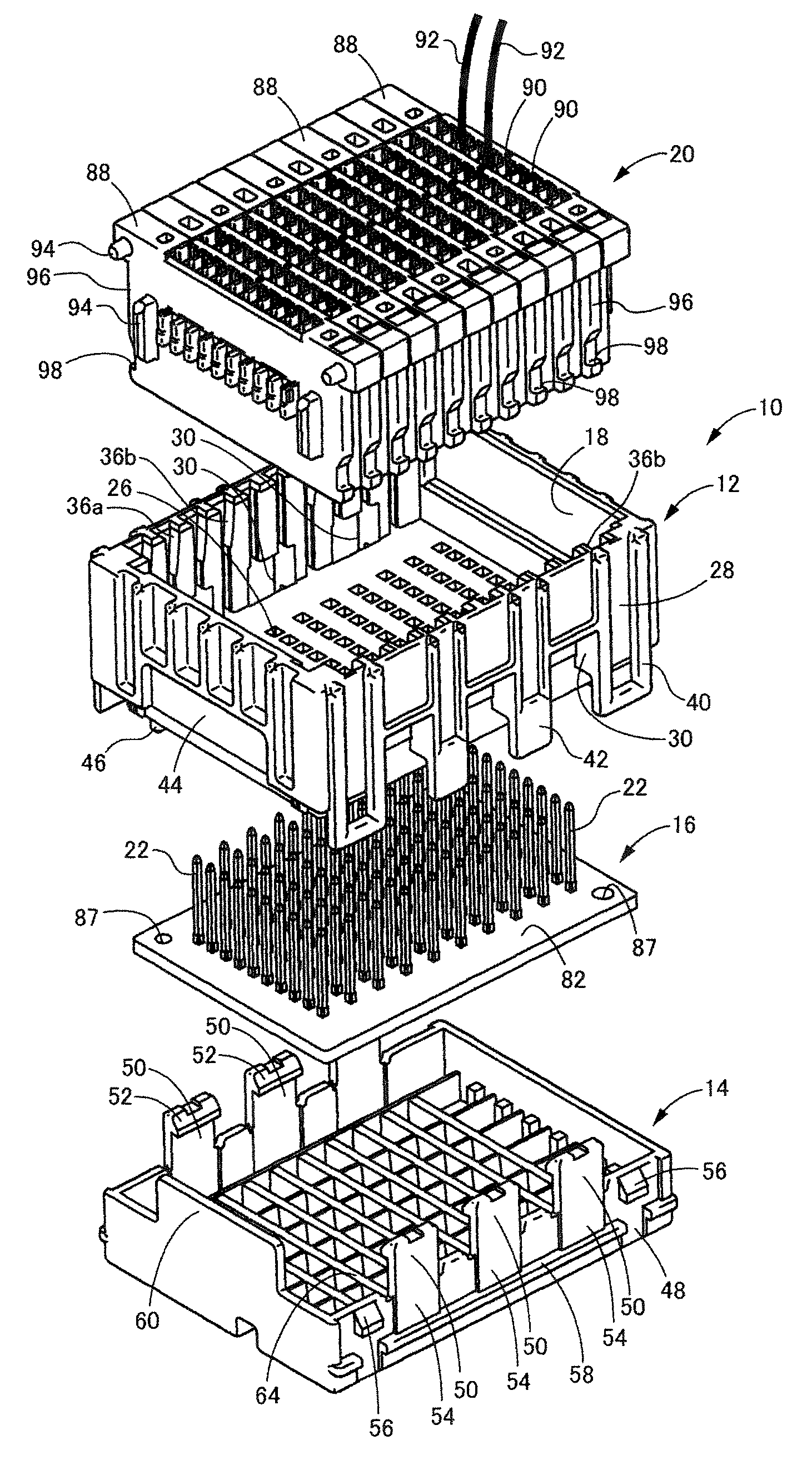
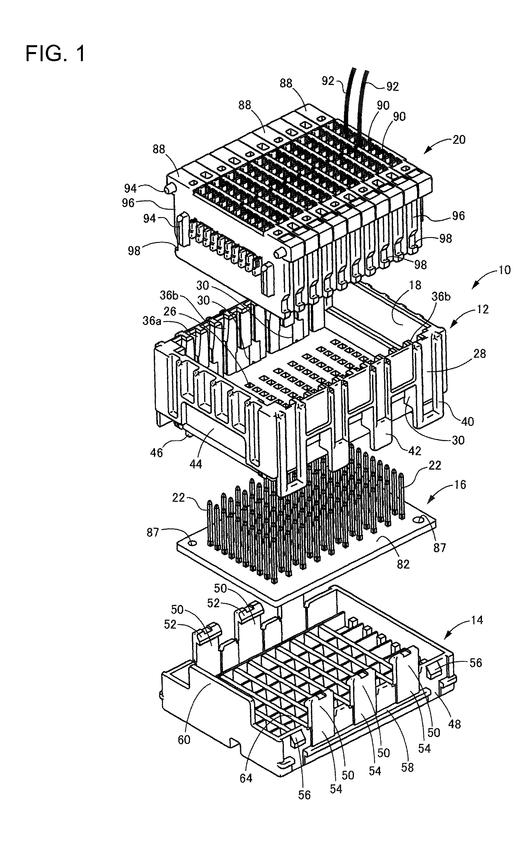
[0032]FIG. 1 shows an electrical junction box 10 according to a first embodiment of the invention. The electrical junction box 10 has a circuit board 16 housed between a first or upper case 12 and a second or lower case 14. A stacked connector 20 is housed in a receptacle 18 in the upper case 12 and can be connected to connection terminals 22 projecting from the circuit board 16. The terms upper and lower are used herein to refer to the orientation shown in FIG. 1.

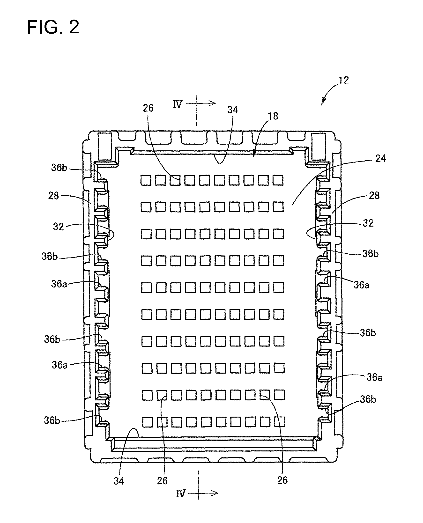
[0033]FIGS. 2 to 4 show the upper case 12. The upper case 12 is molded unitarily from synthetic resin to define a substantially elongated rectangular box that is open at the top. The receptacle 18 is a substantially rectangular void in the open top of the upper case 12.

[0034]The upper case 12 has a bottom wall 24 at the bottom of the receptacle 18 and terminal insertion holes 26 are formed in the bottom wall 24. In the present embodiment, ten terminal insertion holes 26 are formed in a row and are separated by a constant g...


PUM


Abstract

An electrical junction box (10) has a box body (84) is formed by combining a first case (12) and a second case (14). The first case (12) is provided with a receptacle (18) that houses a connector (20). The second case (14) has a connector lock (50) that fixes the connector (20) in the receptacle (18) and a vehicle fixing portion (68) that fixes the box body (84) to a vehicle attachment portion (78).

Description

BACKGROUND OF THE INVENTION[0001]1. Field of the Invention[0002]The invention relates to an electrical junction box for an automobile or the like, and in particular relates to an electrical junction box in which a connector lock for fixing a connector and a vehicle fixing portion for fixation to a vehicle.[0003]2. Description of the Related Art[0004]Electrical junction boxes have been used in automobiles and the like to facilitate the branching of wiring harnesses and connect wiring harnesses to electrical components, such as fuses and relays. U.S. Pat. No. 7,594,830 discloses such an electrical junction box with a box body formed by combining upper and lower cases. A circuit board, such as a printed circuit board, is housed inside the box body, and connection terminals project from the circuit board into a receptacle in the box body. Connectors provided at the terminals of wiring harnesses can be inserted into the receptacle and connected to the connection terminals of the circuit ...

Claims


Application Information

Patent Timeline
Patent Type & Authority Patents(United States)
IPC IPC(8): H01R13/73H01R13/627H01R13/514H01R9/22H01R12/00H01R13/506
CPCH01R13/73H01R13/506H01R13/514H01R13/6273H01R9/223H01R2201/26
Inventor KATSUSE, SHUNSUKE
Owner SUMITOMO WIRING SYST LTD
Learn More