Device for heat-treating sheet metal strips

a technology of sheet metal strips and heat treatment, which is applied in the direction of heat treatment equipment, lighting and heating equipment, furniture, etc., can solve the problems of affecting the strength of the device, the possibility of caking together of the bearing journal in the bearing, and the device is unable to heat treat, etc., to achieve the effect of simple construction conditions and sufficient temperature resistan

Active Publication Date: 2014-11-04
EBNER-INDUSTRIEOFENBAU GMBH
View PDF12 Cites 2 Cited by
  • Summary
  • Abstract
  • Description
  • Claims
  • Application Information

AI Technical Summary

Benefits of technology

[0008]By providing an insert with a sliding layer between the bearing journal and the journal receptacle of the bearing, caking of the bearing journal in the journal receptacle can be prevented in a simple way, so that the sliding accommodation of the bearing journal in the bearing can be ensured even at high temperatures. The precondition is a sliding layer which has sufficient temperature resistance, as is provided advantageously for example in sliding layers made of a ceramic material. By providing an insert forming the sliding layer in the support area of the bearing journal between the journal receptacle and the journal, simple constructional conditions are obtained because the insert, which is preferably a respectively formed sheet metal part, can simply be coated with a sliding layer as a separate component. Moreover, the sliding layer is subjected to a far from inconsiderable wear and tear as a result of the comparatively high weight loads by the radiant tube unit, so that an exchangeable insert forming the sliding layer would entail special advantages when it is intended to renew the sliding layer. It is merely necessary to remove the insert and to replace the same with a newly coated one or by a new insert.

Problems solved by technology

As a result of the high treatment temperatures of 750° C. to 900° C. for example, the strength even of high-temperature steel will suffer, leading to the likelihood of caking together of the bearing journal in the bearing.
The prevention of the axial journal movement in the bearing leads to deformations of the radiant tubes and consequently to damage which can lead to a standstill of the device.

Method used


Image

  • Device for heat-treating sheet metal strips
  • Device for heat-treating sheet metal strips
  • Device for heat-treating sheet metal strips

Examples


Embodiment Construction

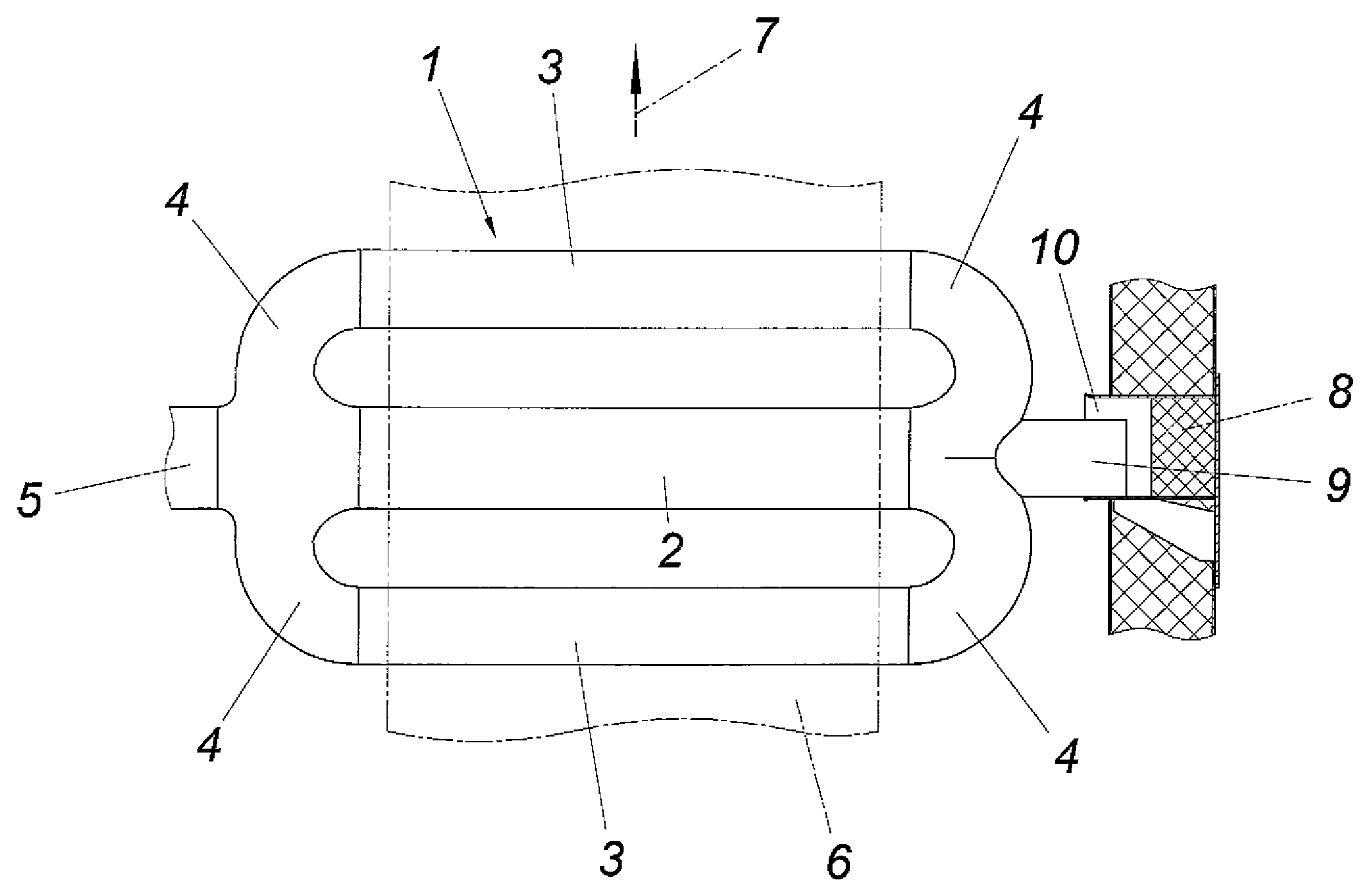
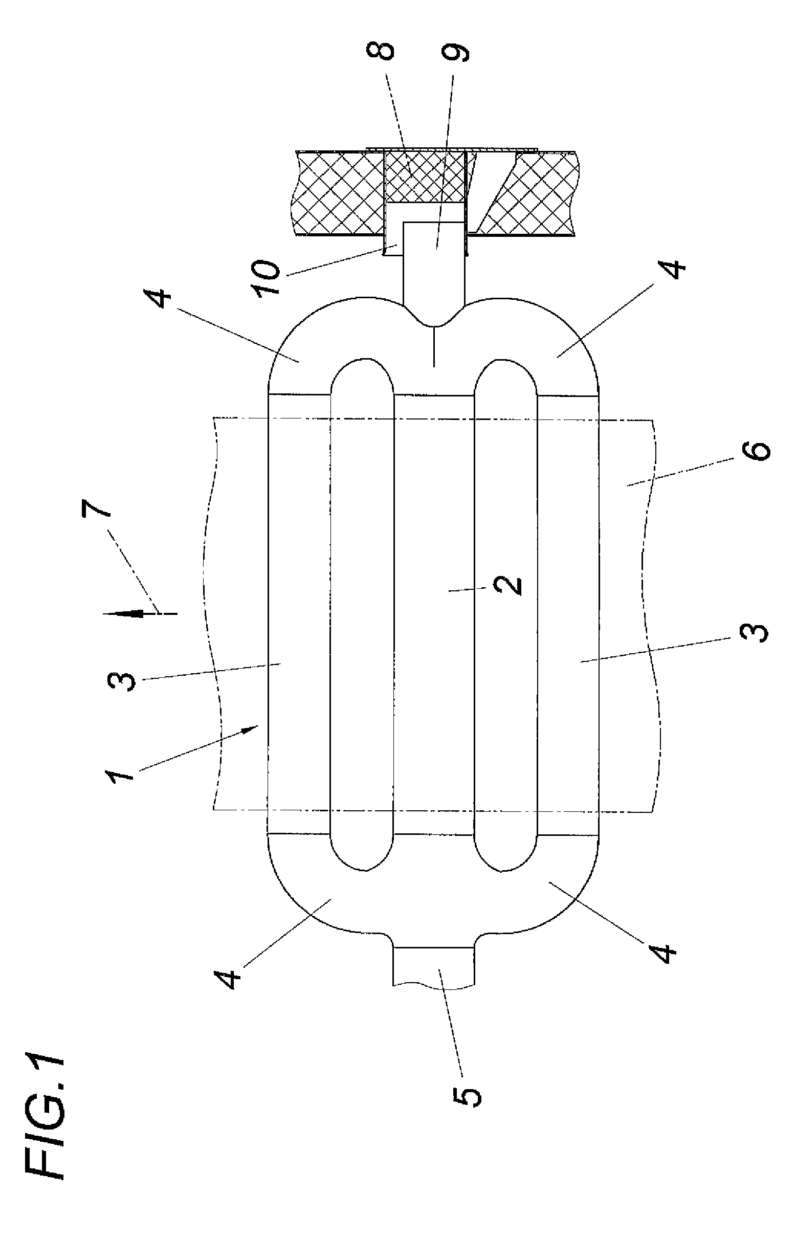
[0013]The illustrated device for the heat treatment of sheet metal strips comprises according to FIG. 1 at least one radiant tube unit 1 which comprises a middle tube 2 and two parallel outer tubes 3 which are disposed together with the middle tube 2 in a common axial plane. The outer tubes 3 are respectively flow-connected to the middle tube 2 via tube bends 4 at the end side. The hot exhaust gases flowing into the middle tube 2 from a burner connected to an extension 5 of the middle tube 2 are therefore partly guided in a circuit via the two outer tubes 3. A sheet metal strip 6 which is indicated by a dot-dash line is heated by means of the radiation heat emitted by the tubes 2, 3, which sheet metal strip is guided parallel to the common axial plane of the tubes 2, 3, namely in a direction of feed 7 which extends transversely to the tube axes.

[0014]The radiant tube unit 1 is mounted on both sides of the tubes 2 and 3, so that a substantially even distribution of the weight load is...


PUM

PropertyMeasurementUnit
temperaturesaaaaaaaaaa
thermal expansionsaaaaaaaaaa
strengthaaaaaaaaaa

Abstract

A device is described for heat-treating sheet metal strips (6), comprising at least one radiant tube unit (1) which has three tubes disposed in a common plane parallel to the sheet metal strip (6), namely a middle tube (2) that can be connected to a burner and two outer tubes (3) that are connected at both ends to the middle tube (2) by means of tube bends (4), and a bearing (8) on the side of the radiant tube unit (1) opposite the burner for a bearing journal (9) connected to the two tube bends (4) between the middle tube (2) on the one hand and the two outer tubes (3) on the other hand, the bearing journal engaging in a journal receptacle (10) of the bearing (8) in an axially displaceable manner. In order to provide advantageous constructional conditions it is proposed that an insert (16) forming a sliding layer (15) is provided in the support area of the bearing journal (9) between the journal receptacle (10) of the bearing (8) and the bearing journal (9).

Description

CROSS REFERENCE TO RELATED APPLICATIONS[0001]This application is the National Stage of PCT / AT 2010 / 000340 filed on Sep. 17, 2010 , which claims priority under 35 U.S.C. §119 of Austrian Application No. A 1609 / 2009 filed on Oct. 13, 2009 , the disclosure of which is incorporated by reference. The international application under PCT article 21(2) was not published in English.[0002]1. Field of the Invention[0003]The invention relates to a device for heat-treating sheet metal strips, comprising at least one radiant tube unit which has three tubes disposed in a common plane parallel to the sheet metal strip, namely a middle tube that can be connected to a burner and two outer tubes that are connected at both ends to the middle tube by means of tube bends, and a bearing on the side of the radiant tube unit opposite the burner for a bearing journal connected to the two tube bends between the middle tube on the one hand and the two outer tubes on the other hand, the bearing journal engaging...

Claims


Application Information

Patent Timeline
Patent Type & Authority Patents(United States)
IPC IPC(8): F27D99/00F23C3/00C21D9/54
CPCF27D99/0006F23C3/002F27D99/0035C21D1/00C21D9/52
Inventor EBNER, ROBERTMORBITZER, EDUARD
Owner EBNER-INDUSTRIEOFENBAU GMBH
Why Eureka
Try Eureka