Neutron measurement apparatus and neutron measurement method

a technology of neutron measurement and measurement apparatus, which is applied in the direction of instruments, radiation measurement, measurement devices, etc., can solve the problems of difficult to completely remove the influence of noise, impossible to realize perfect filtering characteristics, etc., and achieve quick and accurate neutron measurement and enhance the effect of implementability on the circuit substra

Active Publication Date: 2014-11-04
KK TOSHIBA
View PDF17 Cites 6 Cited by
  • Summary
  • Abstract
  • Description
  • Claims
  • Application Information

AI Technical Summary

Benefits of technology

[0013]An object of the present invention, which has been made in order to solve the problems according to the conventional art, is to provide a neutron measurement apparatus and a neutron measurement method capable of quickly and accurately obtaining a neutron measurement value from fast Fourier transform (FFT)-processed signals in the frequency domain without receiving influences of noise components.
[0014]Another object of the present invention is to provide a neutron measurement apparatus and a neutron measurement method capable of overcoming time delay due to calculation by eliminating the inverse fast Fourier transform (iFFT) processing after the fast Fourier transform (FFT) processing during the neutron measurement, thereby enhancing implementation to circuit substrates constituting the apparatus.
[0021]The neutron measurement apparatus and the neutron measurement method of the present invention employ the FFT processing in the neutron measurement, so as to convert the power spectral densities of FFT-processed signals in the frequency domain to obtain a neutron measurement value, thereby realizing quick and accurate neutron measurement without including noise components.
[0022]In the present invention, it is possible to obtain a neutron measurement value based on the power spectral density of a signal in the frequency domain without converting the FFT-processed signal in the frequency domain into the signal in the time domain through the iFFT processing. Accordingly, it is unnecessary to implement the iFFT device, thereby enhancing implementability to the circuit substrates.

Problems solved by technology

In conventional analogue filters, infinite impulse response (IIR) filters or finite impulse response (FIR) filters that perform digital filtering in the time domain, it is impossible to realize perfect filtering characteristic, and it is difficult to completely remove influences of noises.

Method used


Image

  • Neutron measurement apparatus and neutron measurement method
  • Neutron measurement apparatus and neutron measurement method
  • Neutron measurement apparatus and neutron measurement method

Examples


first embodiment

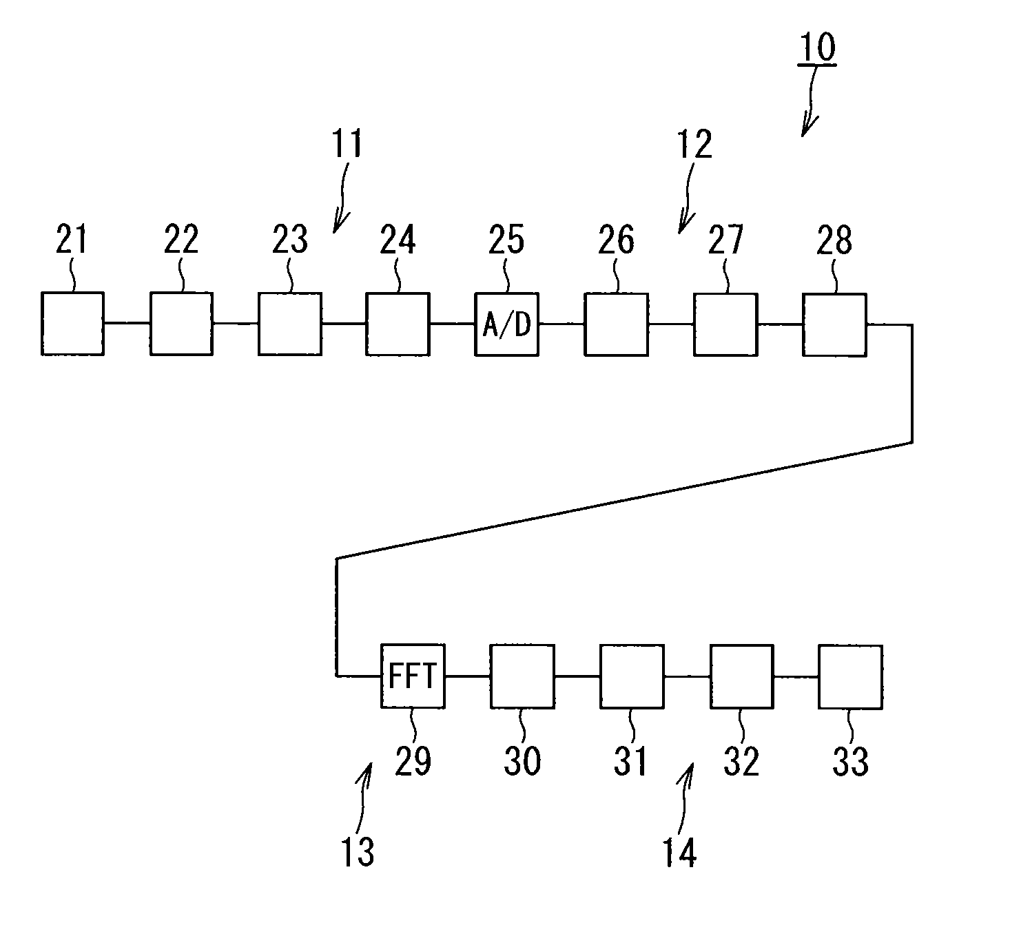
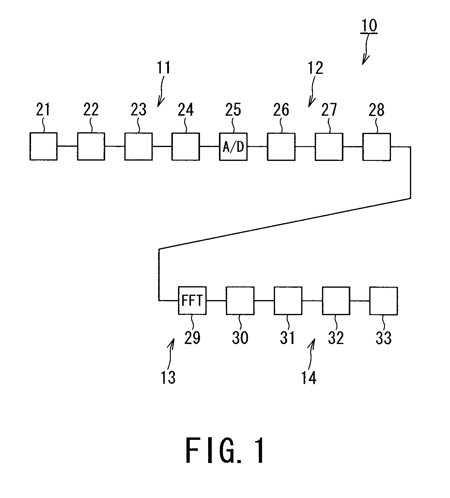
[0032]FIG. 1 is a schematic diagram showing a first embodiment of a neutron measurement apparatus and a neutron measurement method.

[0033]The neutron measurement apparatus and the neutron measurement method exemplified in the present embodiment are used in measurement of neutrons generated in a nuclear fission reactor such as a light-water reactor and a nuclear fusion reactor in a nuclear power plant.

[0034]A neutron measurement apparatus 10 shown in FIG. 1 is applied to a Campbell measurement apparatus for measuring neutrons with the Campbell's method. This neutron measurement apparatus 10 focuses on that statistical fluctuation of detector output signals from a neutron detector is equivalent to the power spectrum, and performs the neutron measurement based on the following new findings that the detector output signal in the time domain is processed through the fast Fourier transform (FFT) into a signal in the frequency domain, and thereafter, the signal in the frequency domain is fi...

second embodiment

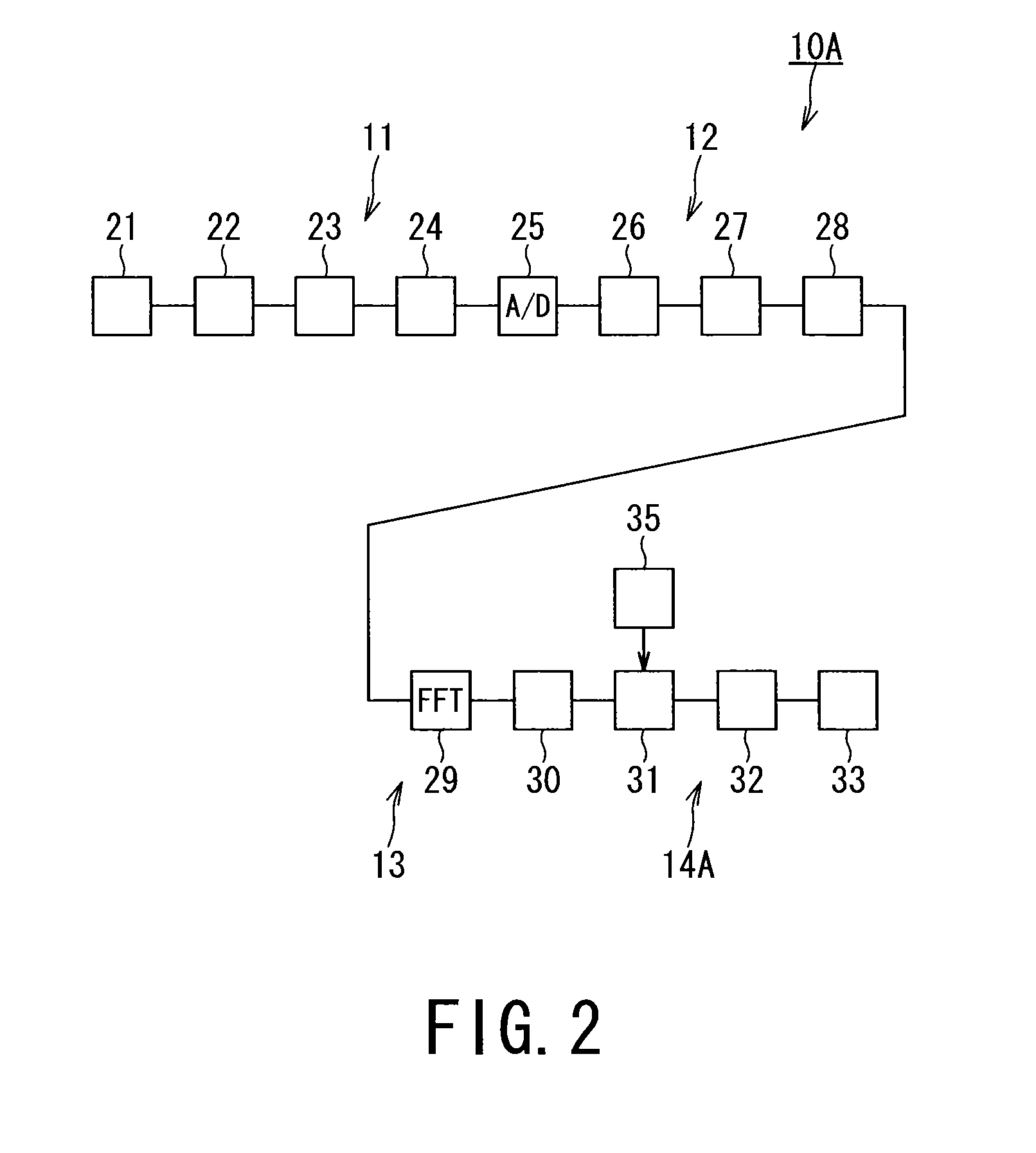
[0059]FIG. 2 is a schematic diagram showing a second embodiment of a neutron measurement apparatus and a measurement method.

[0060]The outline of the configuration of the neutron measurement apparatus and the measurement method exemplified in the second embodiment includes a signal processing system 14A that further includes a signal-selection range switching unit 35 in the signal processing system 14 of the first embodiment, and the other configurations are the same as those of the first embodiment; thus the same constituent elements and operations are designated with the same numeral references, and their redundant description will be omitted or simplified.

[0061]The neutron measurement apparatus 10A of the second embodiment is configured to convert the signals in the time domain into the signals in the frequency domain through the fast Fourier transform (FFT) on the FFT device 29, and thereafter, select the selection range of the signals in the frequency domain on the signal-select...

third embodiment

[0068]FIG. 3 is a schematic diagram showing a third embodiment of a neutron measurement apparatus and a measurement method.

[0069]In the description of the neutron measurement apparatus 10B exemplified in the third embodiment, the same constituent elements as those of the neutron measurement apparatus 10 exemplified in the first embodiment are designated with the same numeral references and their redundant description will be omitted or simplified. The signal processing system of the neutron measurement apparatus 10B of the third embodiment has the same constituent elements as the signal processing system 14A of the neutron measurement apparatus 10A of the second embodiment, and these same constituent elements are designated with the same numeral references, and their redundant description will be omitted or simplified.

[0070]A digitizing processing system 12B of the neutron measurement apparatus 10B of the third embodiment has a different configuration from that of the digitizing pro...


PUM


Abstract

A neutron measurement apparatus includes: an analog signal processor; a digitizing processor; an FFT calculation processor; and a signal processor. The analog signal processor amplifies alternating current components of detector output signals output from a neutron detector, and filters to remove high frequency components from the output signals, which the digitizing processor digitizes at a constant sampling period in a time series; the FFT calculation processor converts certain of the signals in a time domain from the digitizing processor into signals in a frequency domain, and filters the signals in the frequency domain; and the signal processor selects and extracts signals having required frequency components through the calculation processing on the FFT calculation processor, to calculate power spectral densities of the extracted signals, and to convert the calculated power spectral densities into a neutron measurement value.

Description

CROSS-REFERENCE TO RELATED APPLICATIONS[0001]This application is based upon and claims the benefit of priority from Japanese Patient application No. 2012-043995, filed on Feb. 29, 2012, the entire contents of each of which are incorporated herein by reference.BACKGROUND OF THE INVENTION[0002]1. Field of the Invention[0003]Embodiments of the preset invention relate to a measurement technique to measure neutrons generated in a nuclear fission reactor and a nuclear fusion reactor.[0004]2. Description of the Related Art[0005]Neutrons generated in a nuclear fission reactor of a light-water reactor in a commercial nuclear power plant are measured by use of fission counter tubes because of their excellent discrimination performance to discriminate neutrons from gamma rays. In a state of a low reactor power, output signals from the fission counter tubes are measured as pulse signals. In a state of a relatively high reactor power, the output signals from the fission counter tubes cannot be i...

Claims


Application Information

Patent Timeline
Patent Type & Authority Patents(United States)
IPC IPC(8): G01T3/00
CPCG01T3/00G01T1/17
Inventor KONO, SHIGEHIROTOMITAKA, MAKOTO
Owner KK TOSHIBA
Why Eureka
Try Eureka