By way of background, the volume of traffic in industrialized countries has reached levels that lead to time-costing traffic
jams that may be caused by even the slightest traffic irregularities.
Although an accident happens in a few seconds, making an accident report involves a great deal of time, sometimes several hours or more.
At the present state-of-the-art, the tools being used to
record / document the evidence immediately after the accident usually are incapable of providing the completeness and accuracy needed to adequately describe and the present the evidence.
1. The known on-site “Distance / Angle Measuring Method” is described in “Technische Analyse von Verkehrsunf{dot over (a)}llen”; Danner / Halm; Eurotax AG 1994, ISBN 3-9520040-5-7 (title engl. transl.: Technical Analysis of Motor Vehicle Accidents) which also includes the sub-variations “Triangular Measuring Method”, “Right Angle—Coordinates Method” and the “Chord—Height Measurement”. According to this reference, distances are measured from a centered, fixed point to the various items on the site. There are different applications in use, but all of them go back to the basic idea, wherein distance is measured from a certain point to another and the angle is determined. Later these measurements are transferred and recalculated into real two-dimensional drawings. The angle is measured using a special apparatus to determine the angle by taking aim at the item with a notch. The described method is very insecure, and failures are not detected until the end of the day. Furthermore, it is impossible to add measurements later to the original sketch.
2. Another known on-site measuring method is described in “Lasergestüitzte Vermessung von Unfallstellen”; Verkehrsunfall—und Fahrzeugtechnik; Kardelke, Diederichsen, Laicher; 05 / 1998; pg. 151 ff; Verlag information, Kippenheim (title eng. transl.:
Laser-assisted Measuring of Accident Sites). This
laser-assisted method is based on
triangulation using
laser to measure distances. The procedure disclosed in this reference is generally as shown and described above, except for the fact that angle and
distance measurement is performed electronically using a
laser or other optical tools like a theodolit (e.g.
Total Station), which is commonly used for surveying landscapes. The
disadvantage of the procedure disclosed by this reference is that one static position is used and that there is a need for a second person to hold the reflector. Furthermore, most marks behind walls or even cars (e.g., positions of persons, traffic signs etc.) cannot be measured from that point. Measuring skid marks or other marks on the road is difficult. The traffic area has to be closed for traffic during measurement and the damaged cars have to be moved away. The
usability of the
system during night, rain and
snow is limited.
3. The “Photographic Method”, also described in “Technische Analyse von Verkehrsunf{dot over (a)}llen”; Danner / Halm; Eurotax AG 1994, ISBN 3-9520040-5-7 (title engl. transl.: Technical Analysis of Motor Vehicle Accidents), differs from the above methods (1) and (2) in that it does not call for on-site measurements. This method derives its measurements from the analysis of photographs taken with a
stereo camera (3-D method). The known Video-assisted Accident and Traffic
Documentation System from DE 199 52 832 A1 also is in the group of “Photographic Methods”. This method disclosed in this reference uses reference objects placed on the road to measure distances and angles based on pictures or videos of accident scene. A
disadvantage of this technique is that a large amount of time and a large amount of power is needed to analyze these pictures. The
user needs to find a way of taking a photograph from a
high elevation, with all relevant items at the accident scene appearing in the photograph. Usually, there is no opportunity to perform any analysis or obtain any result thereof while the user is still at the accident site, so all analysis is performed off site. This will cause a situation wherein the analysis shows that important marks cannot be measured when items at the site are gone.
The foregoing recognized methods for recording accident sites have the
disadvantage that although the methodology of each
individual analysis may be very accurate, any factual and legal conclusions based on the analysis nevertheless may be incorrect because they are based on measurements that include a very large margin of error.
However, measuring of all three coordinates (x,y,z) of a point is only possible with considerable effort, and then only with large (e.g., greater than 10%) inaccuracies.
If all evidence of the accident is not completely and accurately recorded initially, usually it will not be possible to do so later because the original evidence as it existed immediately after the accident is no longer available.
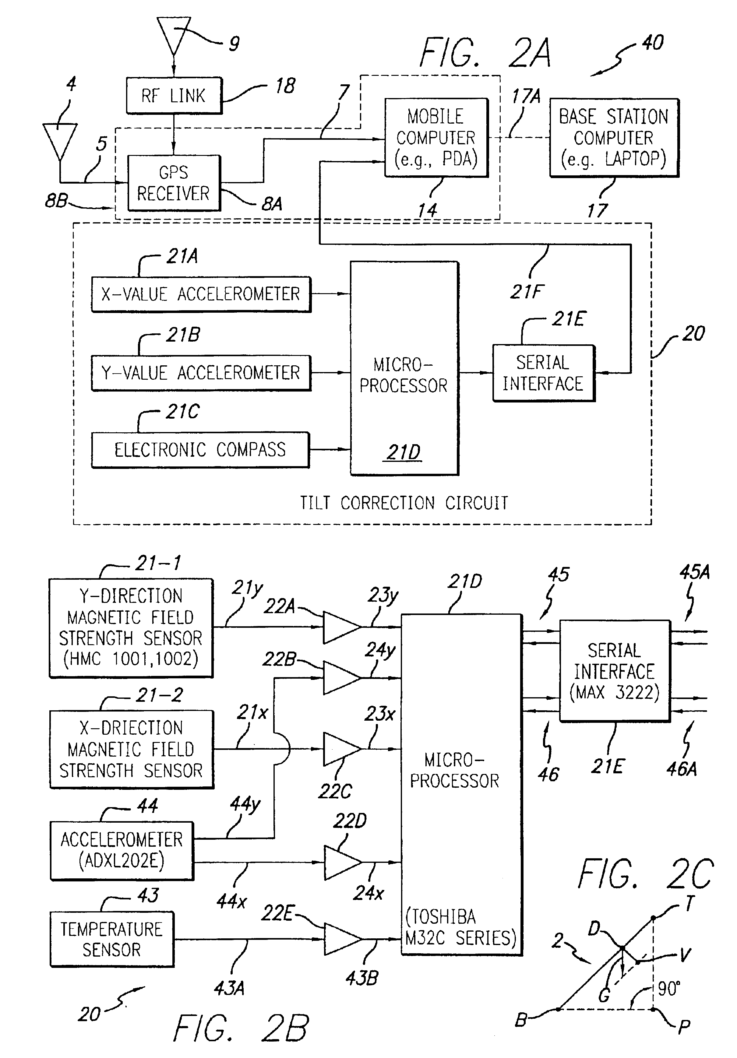
However, GPS techniques have not previously been used to provide measurement of the coordinates of certain points on the vehicles and other items involved in an accident, configurations of damage caused by the accident to vehicles and / or other property, locations and dimensions of tire skid marks and / or other disturbances caused by the accident, etc.
This is at least partly because prior GPS solutions are much too expensive.
This prior art
system has shortcomings that include using low-cost GPS receivers with poor position accuracies requiring use of Kalman filtering techniques that are used to determine average optimum position solutions with noisy input data and which do not provide a real absolute position accuracy.
This procedure does not allow an immediate on-scene check to determine validity of the accident scene measurements.
All related
software packages are commercially available off-the-shelf products which will accept measured
GPS data and are limited in their application to accident
documentation.
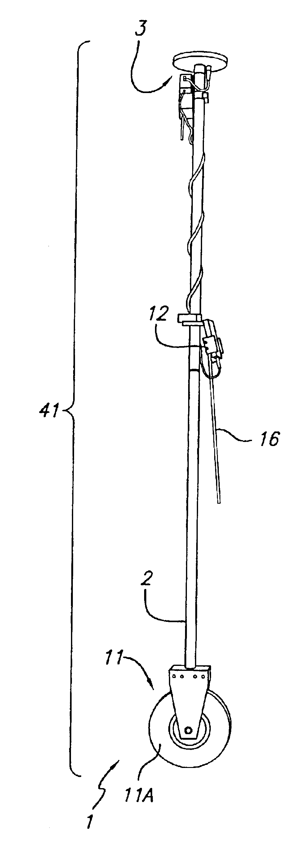
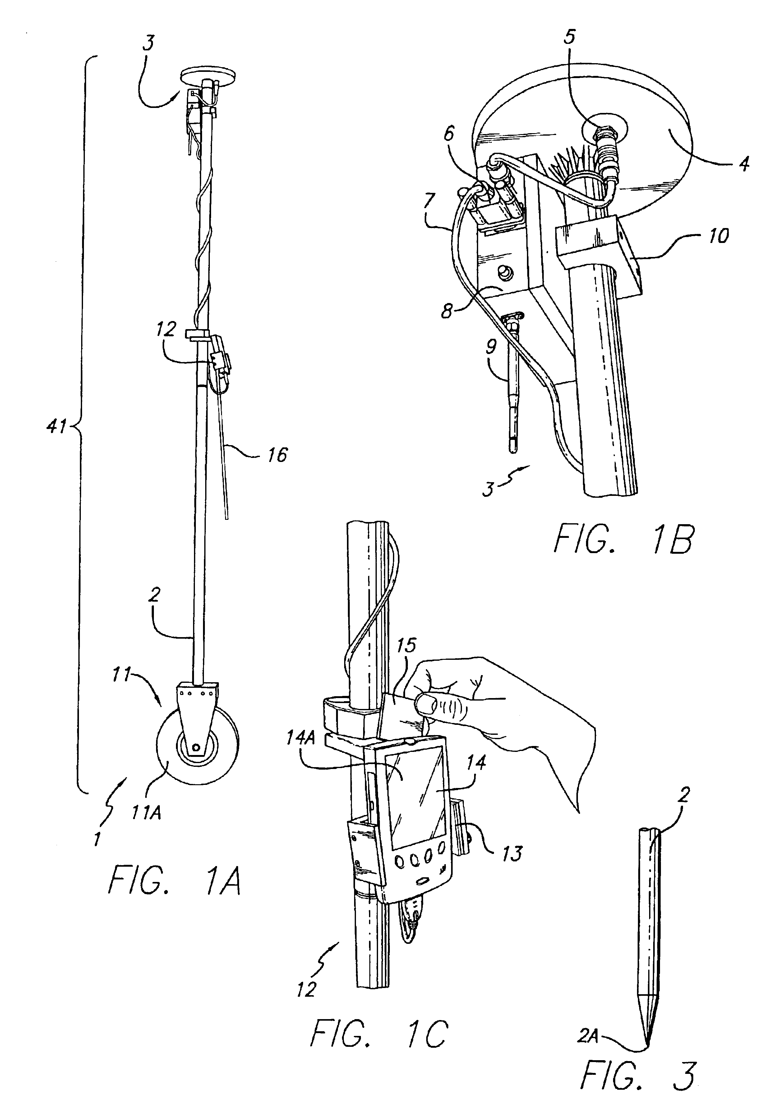
This method results in large measurement errors, and the measurement pole and
electronics cannot be accurately used to measure points
above ground level.

