Neutron measurement apparatus and neutron measurement method
a technology of neutron measurement and measurement apparatus, which is applied in the direction of instruments, radiation measurement, measurement devices, etc., can solve the problems of difficult to completely remove the influence of noise, impossible to realize perfect filtering characteristics, etc., and achieve quick and accurate neutron measurement and enhance the effect of implementability on the circuit substra
- Summary
- Abstract
- Description
- Claims
- Application Information
AI Technical Summary
Benefits of technology
Problems solved by technology
Method used
Image
Examples
first embodiment
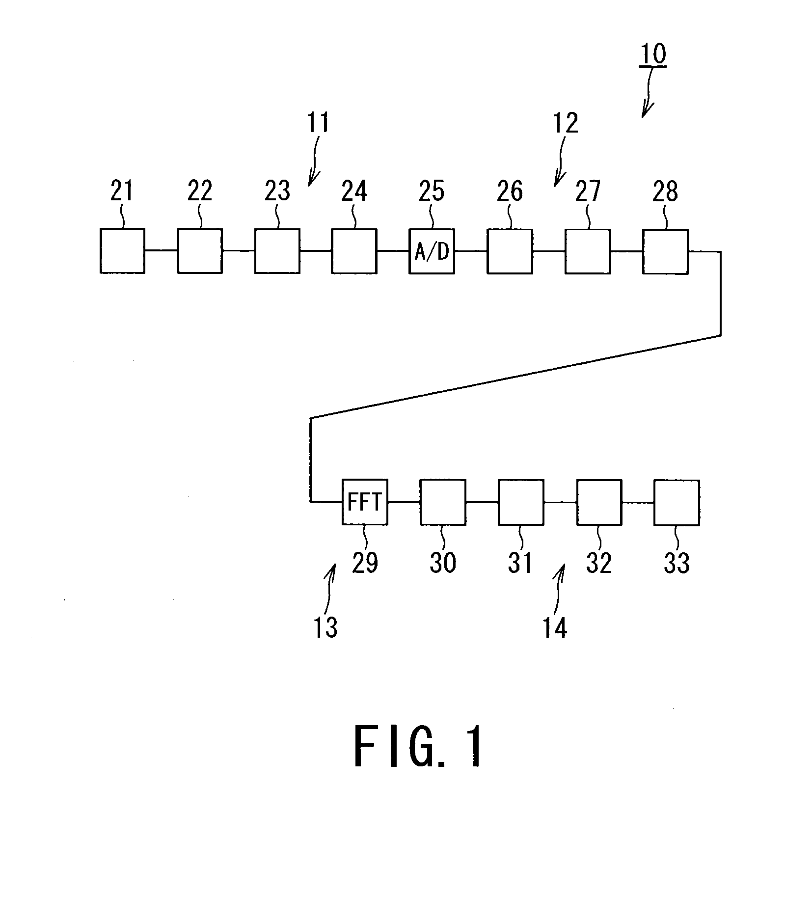
[0032]FIG. 1 is a schematic diagram showing a first embodiment of a neutron measurement apparatus and a neutron measurement method.
[0033]The neutron measurement apparatus and the neutron measurement method exemplified in the present embodiment are used in measurement of neutrons generated in a nuclear fission reactor such as a light-water reactor and a nuclear fusion reactor in a nuclear power plant.
[0034]A neutron measurement apparatus 10 shown in FIG. 1 is applied to a Campbell measurement apparatus for measuring neutrons with the Campbell's method. This neutron measurement apparatus 10 focuses on that statistical fluctuation of detector output signals from a neutron detector is equivalent to the power spectrum, and performs the neutron measurement based on the following new findings that the detector output signal in the time domain is processed through the fast Fourier transform (FFT) into a signal in the frequency domain, and thereafter, the signal in the frequency domain is fi...
second embodiment
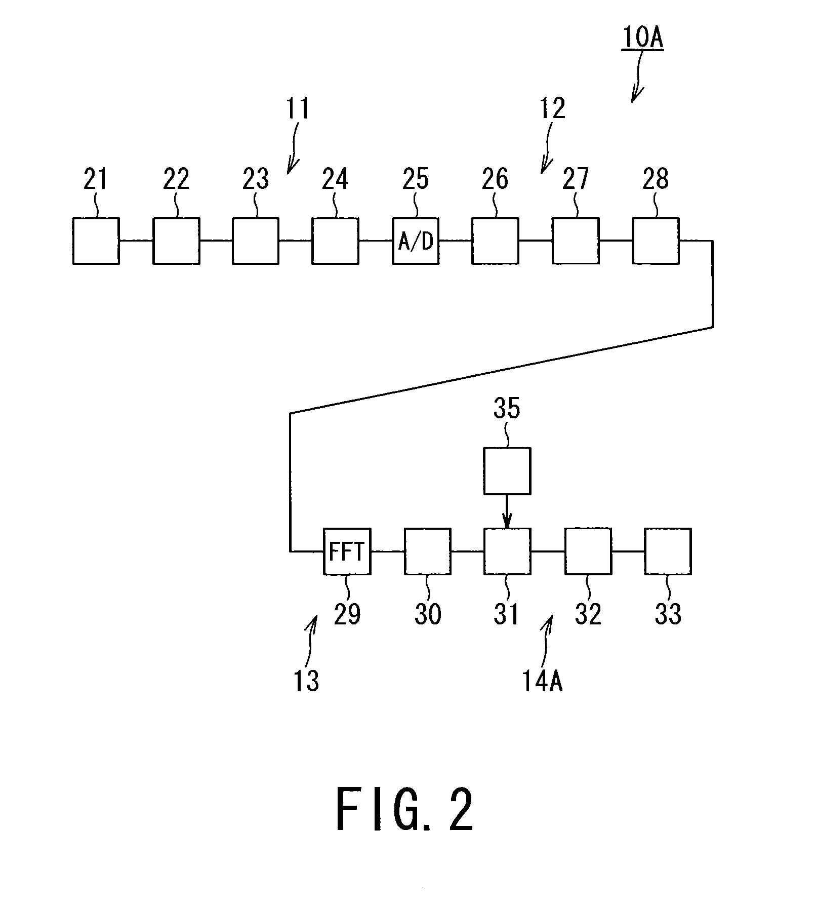
[0057]FIG. 2 is a schematic diagram showing a second embodiment of a neutron measurement apparatus and a measurement method.
[0058]The outline of the configuration of the neutron measurement apparatus and the measurement method exemplified in the second embodiment includes a signal processing system 14A that further includes a signal-selection range switching unit 35 in the signal processing system 14 of the first embodiment, and the other configurations are the same as those of the first embodiment; thus the same constituent elements and operations are designated with the same numeral references, and their redundant description will be omitted or simplified.
[0059]The neutron measurement apparatus 10A of the second embodiment is configured to convert the signals in the time domain into the signals in the frequency domain through the fast Fourier transform (FFT) on the FFT device 29, and thereafter, select the selection range of the signals in the frequency domain on the signal-select...
third embodiment
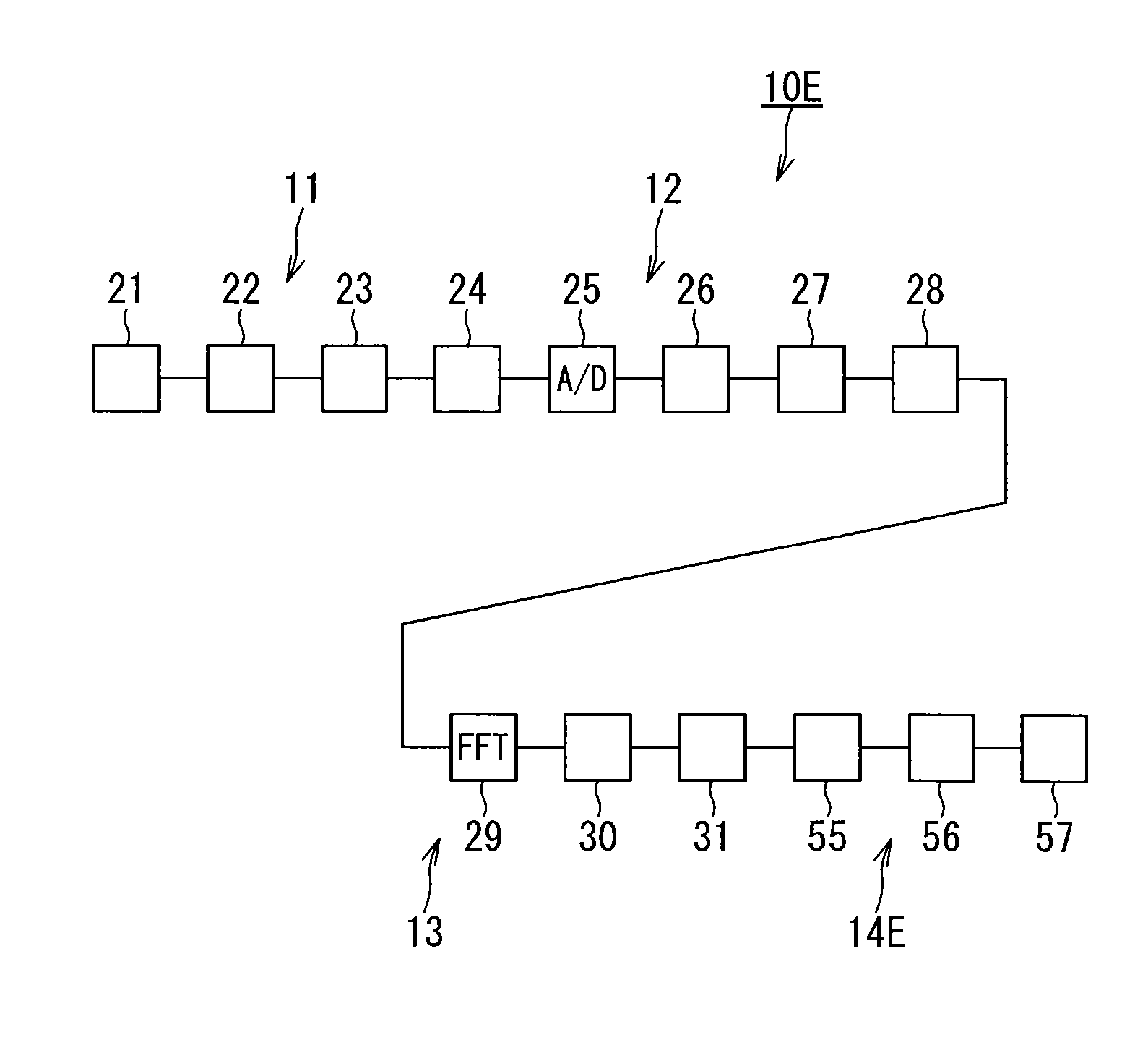
[0066]FIG. 3 is a schematic diagram showing a third embodiment of a neutron measurement apparatus and a measurement method.
[0067]In the description of the neutron measurement apparatus 10B exemplified in the third embodiment, the same constituent elements as those of the neutron measurement apparatus 10 exemplified in the first embodiment are designated with the same numeral references and their redundant description will be omitted or simplified. The signal processing system of the neutron measurement apparatus 10B of the third embodiment has the same constituent elements as the signal processing system 14A of the neutron measurement apparatus 10A of the second embodiment, and these same constituent elements are designated with the same numeral references, and their redundant description will be omitted or simplified.
[0068]A digitizing processing system 12B of the neutron measurement apparatus 10B of the third embodiment has a different configuration from that of the digitizing pro...
PUM
 Abstract
Description
Claims
Application Information
 - R&D
- Intellectual Property
- Life Sciences
- Materials
- Tech Scout
- Unparalleled Data Quality
- Higher Quality Content
- 60% Fewer Hallucinations
Browse by: Latest US Patents, China's latest patents, Technical Efficacy Thesaurus, Application Domain, Technology Topic, Popular Technical Reports.
© 2025 PatSnap. All rights reserved.Legal|Privacy policy|Modern Slavery Act Transparency Statement|Sitemap|About US| Contact US: help@patsnap.com


