Packing element booster

a packing element and booster technology, applied in the direction of sealing/packing, wellbore/well accessories, fluid removal, etc., can solve the problems of unseated packing elements, internal pressure of packing elements now below the initial level, and the potential for at least partial unseating of packing elements

Active Publication Date: 2014-11-11
WEATHERFORD TECH HLDG LLC
View PDF108 Cites 19 Cited by
  • Summary
  • Abstract
  • Description
  • Claims
  • Application Information

AI Technical Summary

Benefits of technology

[0008]In one embodiment, the packer includes a boosting assembly adapted to increase the seal load on the packing element above the seal load applied during setting of the packing element.
[0010]In another embodiment, a method of sealing a tubular in a wellbore includes placing a sealing apparatus in the tubular, wherein the sealing apparatus includes a mandrel; a packing element disposed circumferentially around an outer surface of the mandrel; and a boosting assembly having a housing, a booster sleeve, and a pressure chamber defined by the housing and the booster sleeve. The method also includes expanding the packing element into engagement with the tubular and applying a pressure to the booster sleeve, thereby causing the pressure chamber to reduce in size and the booster sleeve to move the booster sleeve axially to exert a force against the packing element.
[0011]In yet another embodiment, a method of isolating a zone in a wellbore includes providing a sealing apparatus having a first packer and a second packer, wherein at least one of the first packer and the second packer includes a mandrel; a packing element disposed circumferentially around an outer surface of the mandrel; and a boosting assembly having a housing, a booster sleeve, and a pressure chamber defined by the housing and the booster sleeve. The method also includes positioning the sealing apparatus in the wellbore such that the zone is between the first packer and the second packer; expanding the packing element the into engagement with the wellbore; and applying a pressure to the booster sleeve, thereby causing the pressure chamber to reduce in size and the booster sleeve to exert a force against the packing element. In yet another embodiment, the force exerted is greater than a force used to expand the packing element.

Problems solved by technology

A disadvantage with known packer systems is the potential for becoming unseated.
In this regard, wellbore pressures existing within the annular region between an inner tubular and an outer casing string act against the setting mechanisms, creating the potential for at least partial unseating of the packing element.
When the differential pressure approaches or exceeds the initial internal pressure of the packing element, the packing element is compressed further by the differential pressure, thereby causing it to extrude into smaller voids and gaps or exceed the compression strength of the packing element, thereby resulting in a compression set of the packing element.
However, the internal pressure of the packing element is now below the initial level because of the volume transfer and / or compression set of packing element during extrusion.

Method used


Image

  • Packing element booster
  • Packing element booster
  • Packing element booster

Examples


Embodiment Construction

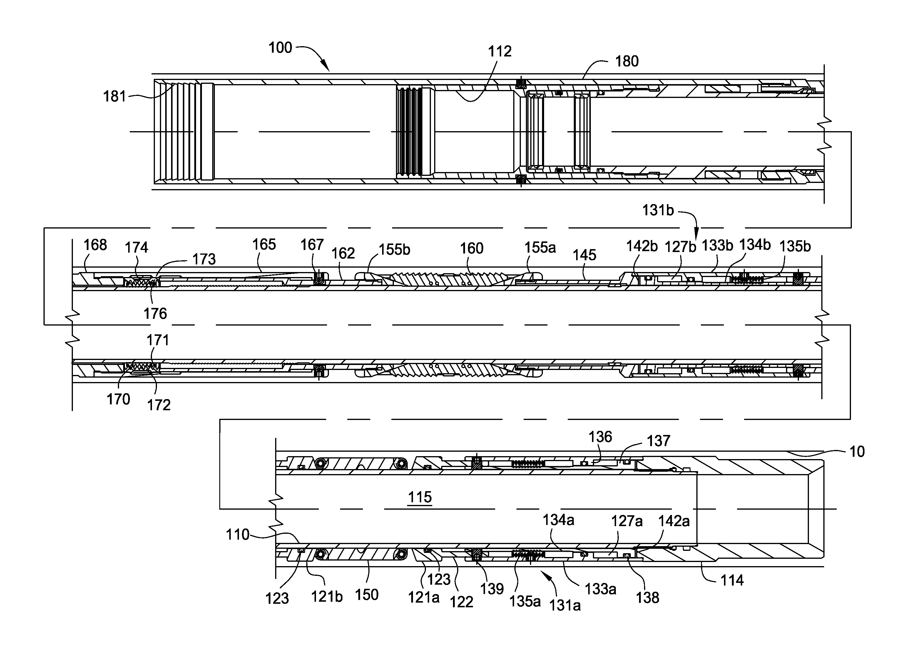
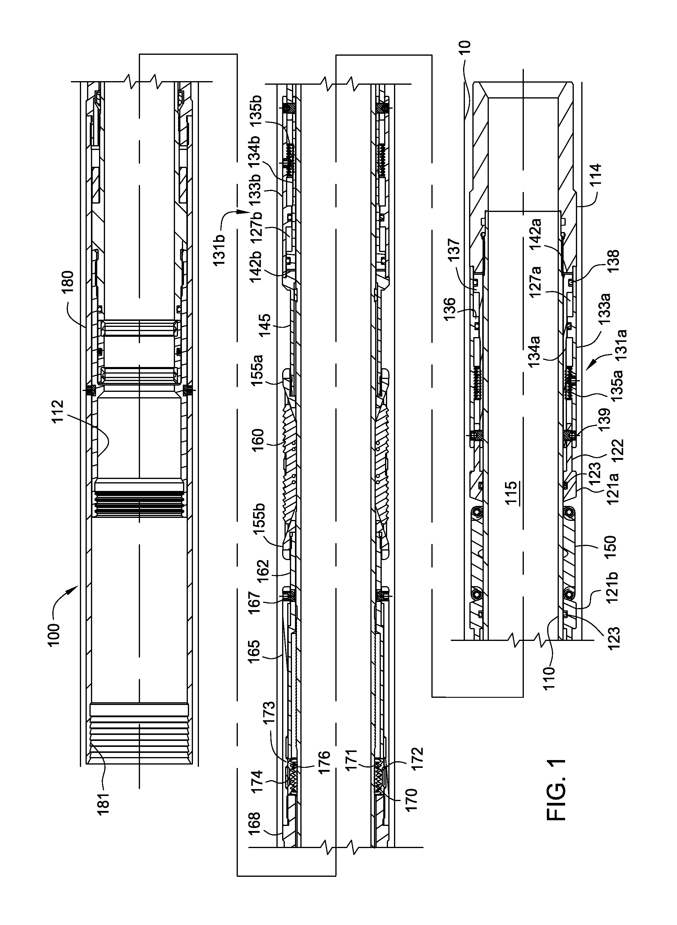
[0024]FIG. 1 presents a cross-sectional view of an embodiment of a packer 100. The packer 100 has been run into a wellbore and positioned inside a string of casing 10. The packer 100 is designed to be actuated such that a seal is created between the packer 100 and the surrounding casing string 10. The packer 100 is run into the wellbore on a work string or other conveying member such as wire line.

[0025]The packer 100 includes a mandrel 110 which extends along a length of the packer 100. The mandrel 110 defines a tubular body that runs the length of the packer 100. As such, the mandrel 110 has a bore 115 therein for fluid communication, which may be used to convey fluids during various wellbore operations such as completion and production operations.

[0026]The mandrel 110 has an upper end 112 and a lower end 114. The upper end 114 may include connections for connecting to a setting tool or work string. The lower end 112 may be connected to a downhole tool which is located at an interm...


PUM


Abstract

A packer is provided for sealing an annular region in a wellbore. In one embodiment, the, packer includes a boosting assembly adapted to increase a pressure on the packing element in response to an increase in a pressure surrounding the packer, for example, an increase in the annulus pressure.

Description

BACKGROUND OF THE INVENTION[0001]1. Field of the Invention[0002]Embodiments of the present invention generally relate to completion operations in a wellbore. More particularly, the present invention relates to a packer for sealing an annular area between two tubular members within a wellbore. More particularly still, the present invention relates to a packer having a bi-directionally boosted and held packing element.[0003]2. Description of the Related Art[0004]During the wellbore completion process, a packer is run into the wellbore to seal off an annular area. Known packers employ a mechanical or hydraulic force in order to expand a packing element outwardly from the body of the packer into the annular region defined between the packer and the surrounding casing. In addition, a cone is driven behind a tapered slip to force the slip into the surrounding casing wall and to prevent packer movement. Numerous arrangements have been derived in order to accomplish these results.[0005]A di...

Claims


Application Information

Patent Timeline
Patent Type & Authority Patents(United States)
IPC IPC(8): E21B23/01E21B33/128E21B33/126E21B33/1295
CPCE21B33/1295E21B33/1285
Inventor INGRAM, GARY, DURON
Owner WEATHERFORD TECH HLDG LLC
Why Eureka
Try Eureka